Wellhead hydraulic drive unit

a hydraulic drive and wellhead technology, applied in the direction of sealing/packing, borehole/well accessories, positive displacement liquid engines, etc., can solve the problem of low installation and retrieval costs

Inactive Publication Date: 2005-02-15
INNOVATIVE PRODN TECH
View PDF10 Cites 33 Cited by
  • Summary
  • Abstract
  • Description
  • Claims
  • Application Information

AI Technical Summary

Benefits of technology

The present invention provides a wellhead hydraulic drive unit to operate various styles of downhole pumps. The drive unit is installed as an integral part of the wellhead thereby eliminating the need for a stuffing

Problems solved by technology

This results in lower insta

Method used


Image

  • Wellhead hydraulic drive unit
  • Wellhead hydraulic drive unit
  • Wellhead hydraulic drive unit

Examples


Embodiment Construction

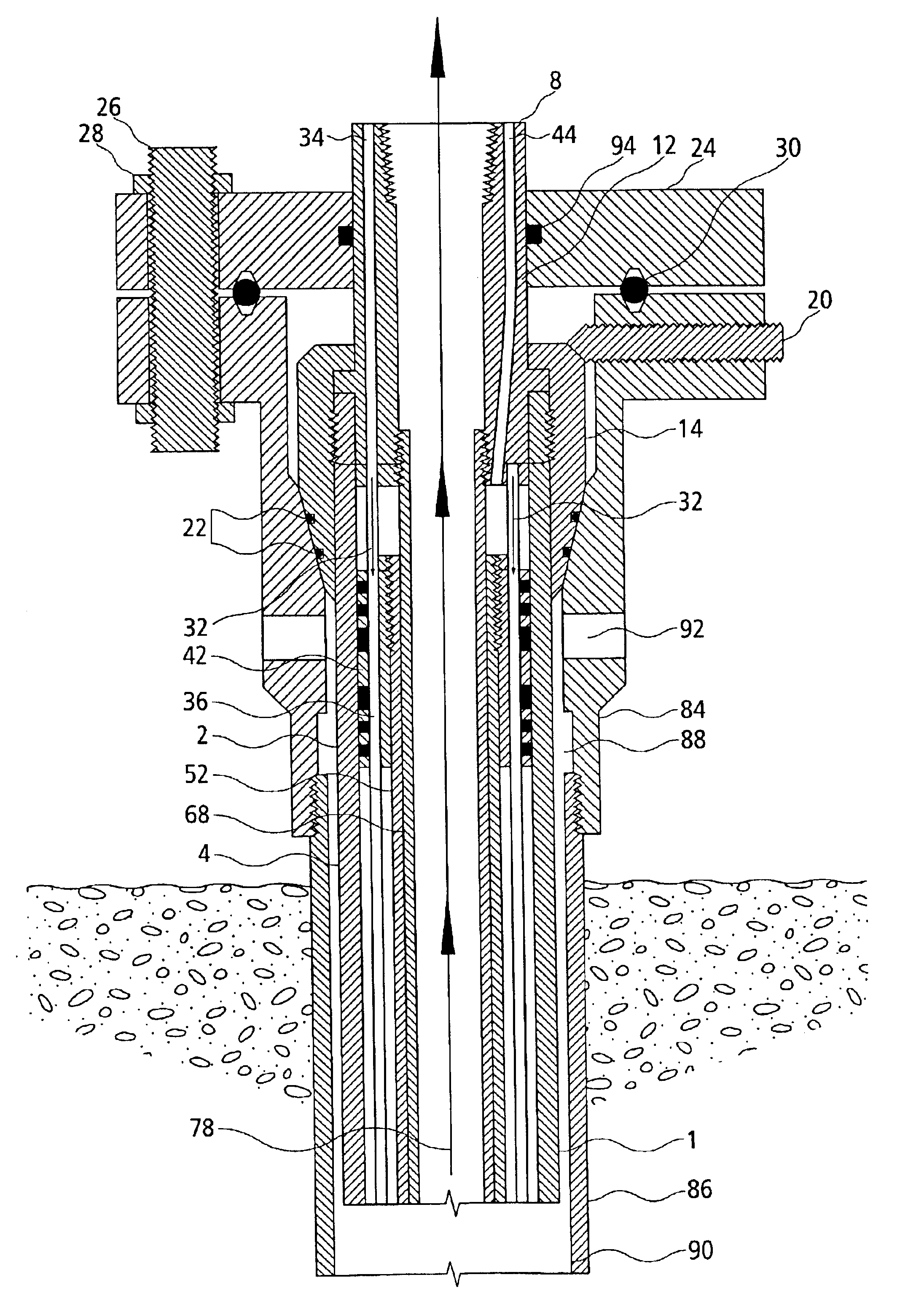
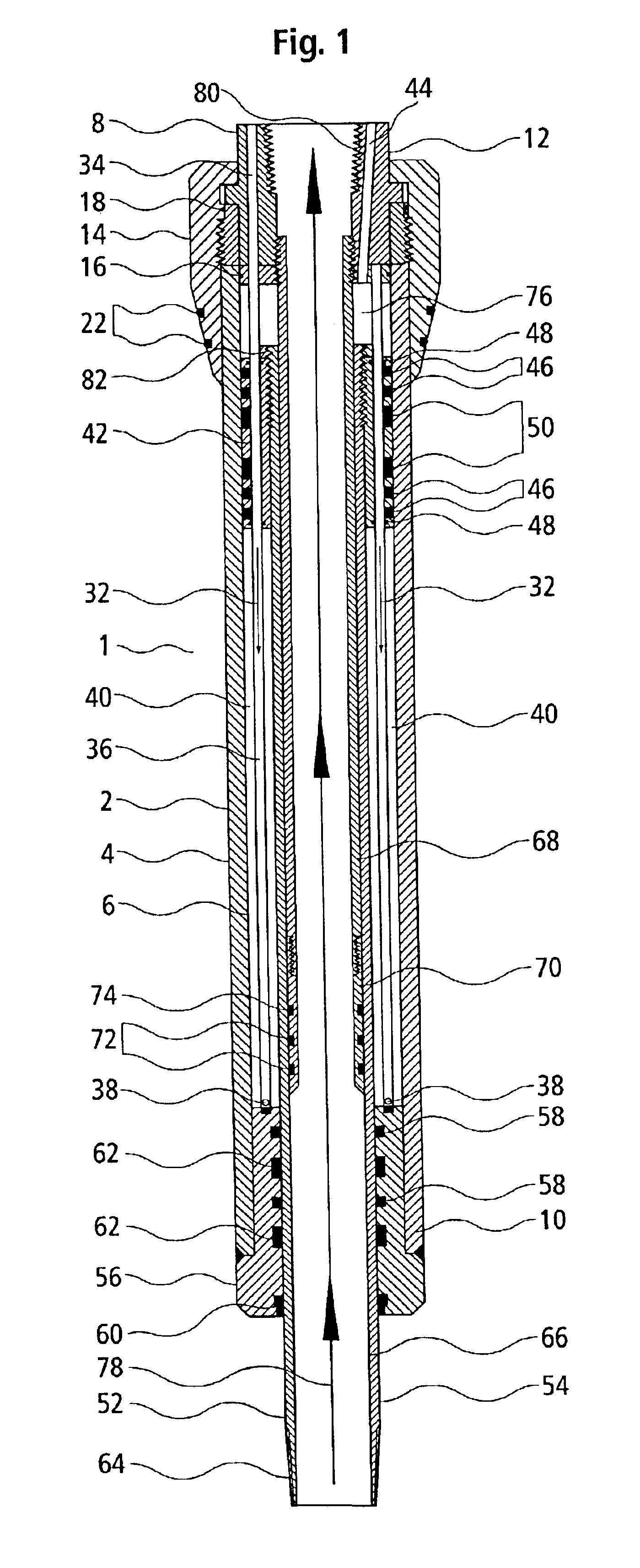
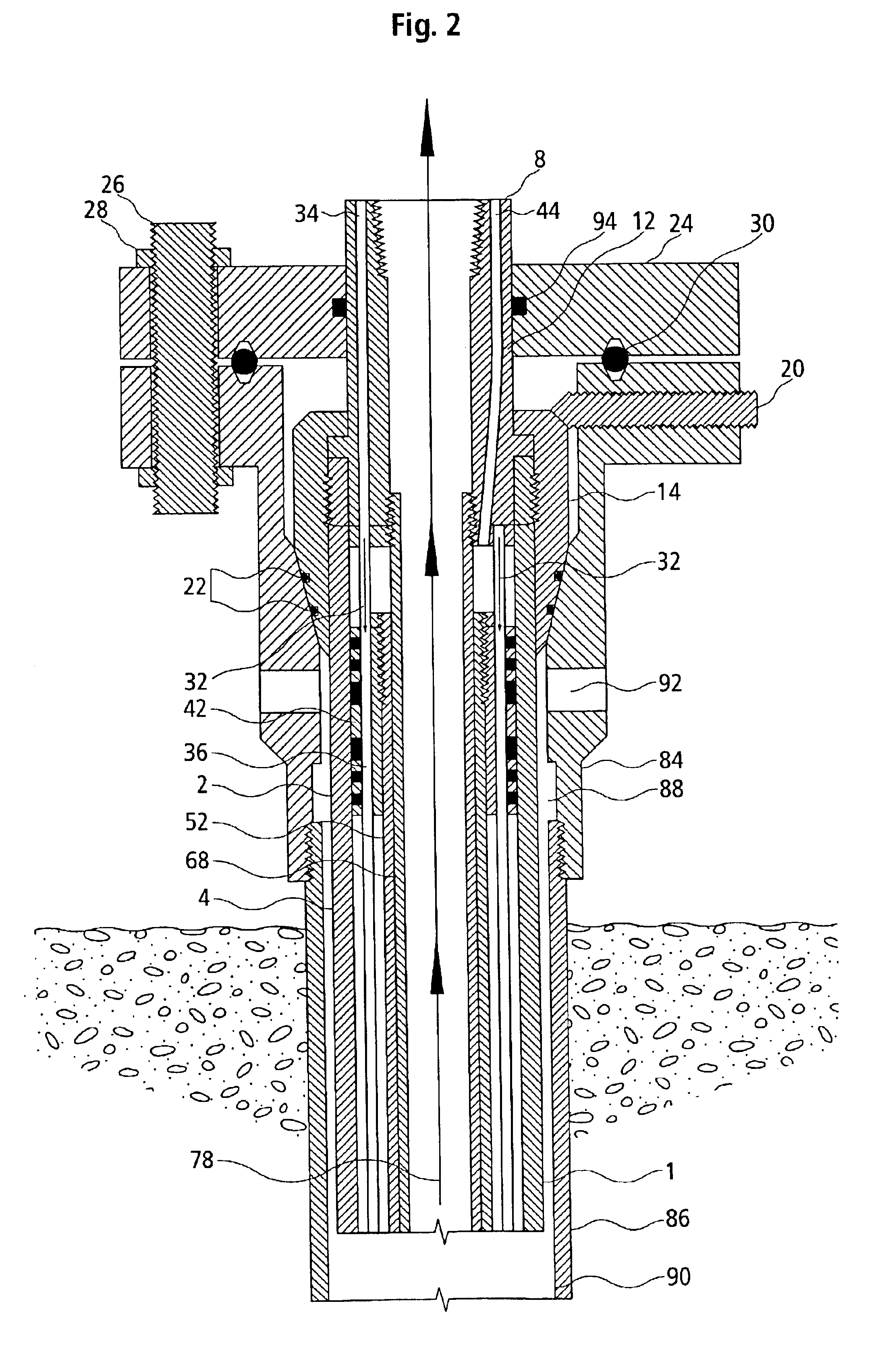
With reference to FIG. 1, the wellhead hydraulic drive unit according to the present invention is shown designated generally by the reference numeral 1. The various parts which make up the drive unit 1 are for the most part housed within hydraulic cylinder 2. Hydraulic cylinder 2 is comprised of cylinder outer wall 4, cylinder inner wall 6, cylinder top end 8 and cylinder bottom end 10.

At cylinder top end 8 is situated top gland 12. Hanger 14 is threaded onto cylinder top end 8 of the hydraulic cylinder 2 to retain top gland 12 to hydraulic cylinder 2. Top gland seal 16 seals top gland 12 to cylinder inner wall 6 and hanger seal 18 seals hanger 14 to cylinder outer wall 4.

It should be noted that hanger 14 profiles vary with different wellheads and are manufactured accordingly. Where applications restrict the use of hanger 14 in the wellhead itself, a landing spool (not shown) can be used. The landing spool is bolted on to the wellhead and the hanger 14 of the wellhead hydraulic driv...


PUM


Abstract

The present invention provides a wellhead hydraulic drive unit to operate various styles of downhole pumps, which is installed as an integral part of a wellhead thereby eliminating the need for a stuffing box. The wellhead hydraulic drive unit comprises a hollow hydraulic cylinder having a piston positioned therein, a hydraulic fluid supply attached to the hydraulic cylinder for raising the piston within the hydraulic cylinder, a hollow ram slideably received within the inner wall of the hydraulic cylinder and connected to the piston for reciprocation in response to the piston; and a production tube inserted through the ram for enabling well fluid to be discharged from the well.

Description

FIELD OF THE INVENTIONThe present invention relates to a drive mechanism associated with artificial lift systems used in the production of oil and other fluids contained within underground formations. More specifically, this invention relates to a wellhead hydraulic drive unit that is installed as an integral part of a wellhead.BACKGROUND OF THE INVENTIONFluid production wells having insufficient pressure are unable to flow liquids to the surface by natural means. Such wells require some form of energy or lift to transfer fluids to the surface.Several artificial lift systems exist to extract the liquids from liquid-bearing reservoirs. In the case of lifting oil from wells, conventional lifting units include the beam pump and the surface hydraulic piston drive. Both of these lift units are situated at the surface of the well and lift fluid to the surface by “stroking” production tubing or rods inside production casing and / or well casing. The production tubing or rods is connected to ...

Claims


Application Information

Patent Timeline
IPC IPC(8): E21B33/03F04B47/04E21B43/12F04B47/00
CPCE21B33/03F04B47/04E21B43/121
Inventor MATTHEWS, EDLACUSTA, GREGGANAKA, JIM
Owner INNOVATIVE PRODN TECH
Why Eureka
Try Eureka