
Flip-top closure with child resistant packaging system

a packaging system and flip-top technology, applied in liquid handling, applications, instruments, etc., can solve the problems of child-resistant packaging, harmful contents, and child-resistant packaging, and achieve the effects of minimizing the amount of modifications, easy and inexpensive manufacturing, and reducing the amount of modifications

Inactive Publication Date: 2005-02-15
SUMMIT PACKAGING SYST INC
View PDF26 Cites 25 Cited by
  • Summary
  • Abstract
  • Description
  • Claims
  • Application Information

AI Technical Summary

Benefits of technology

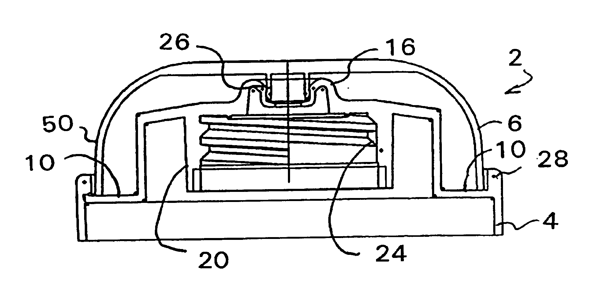
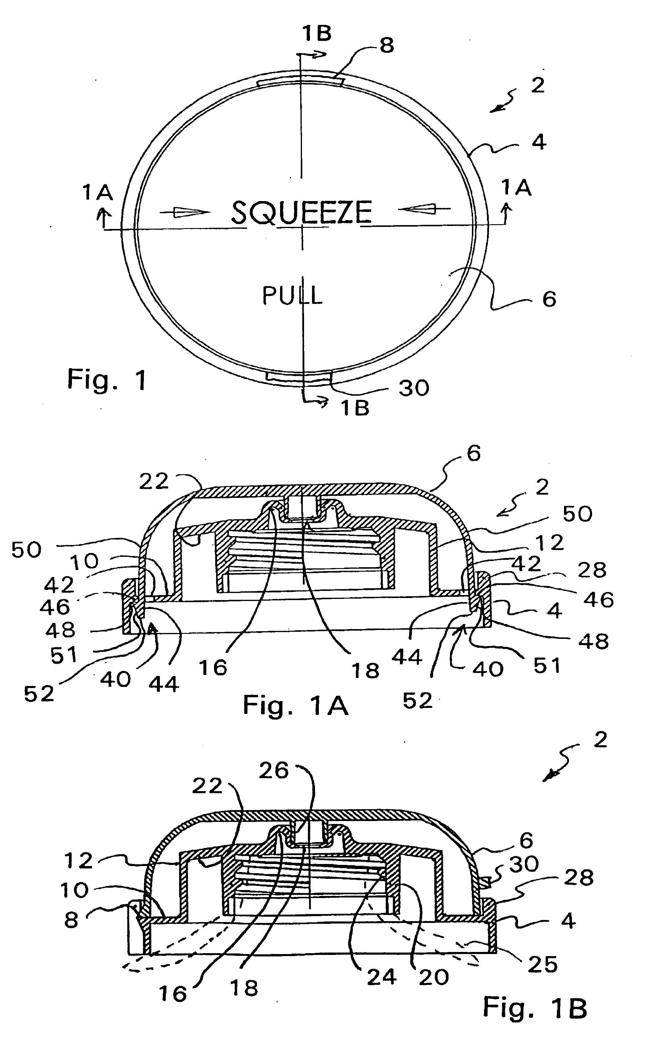
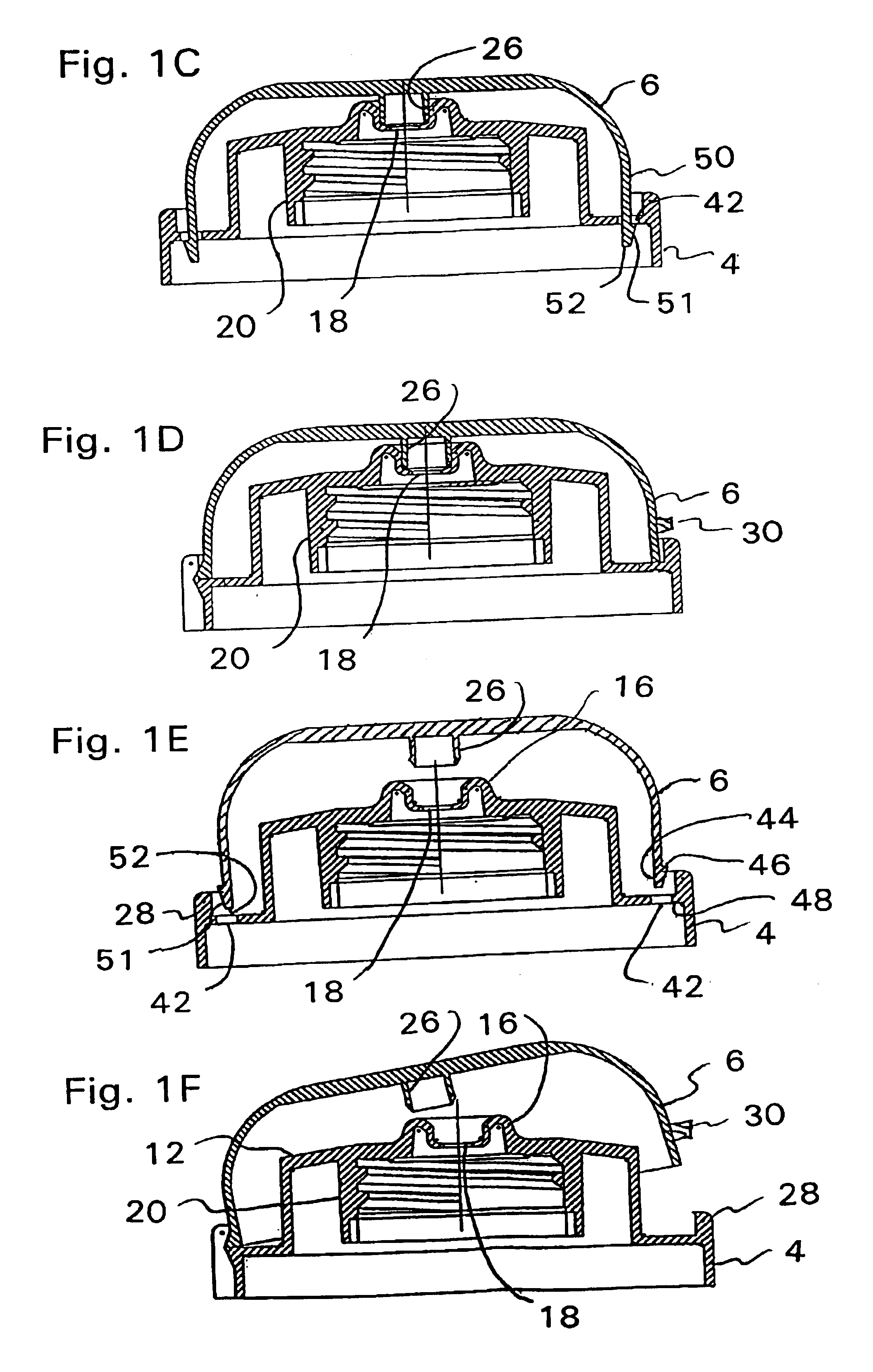
"The present invention provides a flip-top closure with a child resistant packaging system that prevents a child from accessing the product contents or opening the flip-top closure and dispensing a potentially harmful amount of the product contents therefrom. The child resistant packaging system requires a dual action opening sequence in order for the user to unlock the child resistant safety system and open the flip-top closure before dispensing the product contents out through a dispensing orifice provided in the flip-top closure. The invention is easy and inexpensive to manufacture while reliable in preventing an infant or child from either opening the child resistant packaging or, if partially opened, preventing access to a potentially harmful amount of the product contents contained within the package. The invention also minimizes the amount modifications required to adapt conventional flip-top closures."

Problems solved by technology

One drawback associated with currently available flip-top closures is that they can be easily opened by a child and the contents, contained within the container, can be readily dispensed by the child opening the flip-top closure.
Depending upon the contents of the container, if the contents of the container are hazardous and if the child were to contact such hazardous contents with his or her eyes or were in ingest the same, the child could be injured, poisoned, or possibly be killed.
According to government regulations, a child resistant package is one that is designed or constructed to be significantly difficult for children under five to open or obtain a harmful amount of the contents of the child resistant package within a reasonable time.

Method used


Image

  • Flip-top closure with child resistant packaging system
  • Flip-top closure with child resistant packaging system
  • Flip-top closure with child resistant packaging system

Examples


third embodiment

With reference to FIGS. 3-3F, a detailed description concerning the flip-top closure with a child resistance packaging system will now be described. It is to be appreciated that in the following description, the same elements will be provided with the same reference numerals.

As with the first embodiment, the cap 6 is provided with a pair of diametrically opposed mating hook members 44 while the base member 4 is provided with an annular shroud 54 which extends substantially around the entire perimeter of the base member 4. The annular shroud 54 has an inwardly directed annular edge 56 which extends radially inwardly and is located to engage with the respective latching ledges 46 of the hook members 44. The annular edge 56 may have a tapered or chamfered top surface (not shown) to facilitate the annular edge 56 receiving the respective hook members 44. An undersurface of the annular edge 56 forms a mating latching surface 48 which engages with the latching ledges 46 of the respective ...

fourth embodiment

With reference now to FIGS. 4-4C, a detailed description concerning the flip-top closure with a child resistance packaging system will now be described. It is to be appreciated that in the following description, the same elements will be provided with the same reference numerals.

The major difference between this embodiment and the third embodiment is that only a single hook member 44 is provided and the single hook member 44 is located 180° relative to, i.e., diametrically opposite to, the hinge 8. As with the third embodiment, the base member 4 is provided with an annular shroud 54 which extends substantially around the entire perimeter of the base member 4. The annular shroud 54 has an inwardly directed annular edge 56 which extends radially inwardly and is located to engage the latching ledge 46 of the hook member 44. The annular edge 56 has a tapered or chamfered top surface 58 to facilitate the annular edge 56 receiving the hook member 44. An undersurface of the annular edge 56...

fifth embodiment

Turning now to FIGS. 5-5D, a detailed description concerning the flip-top closure with a child resistance packaging system will now be described. It is to be appreciated that in the following description, the same elements will be provided with the same reference numerals.

According to this embodiment, an exterior surface of the cap 6 is provided with a pair of diametrically opposed wings 60 that are generally equally spaced from both the hinge 8 and the handle component 30. A remote free end of each one of the wings 60 supports a downwardly facing hook member 44. The base member 4 is provided with an annular shroud 54 which extends substantially around the entire perimeter of the base member 4. The annular shroud 54 has an inwardly directed annular edge 56 which extends radially inwardly and is located to engage with the respective latching ledges 46 of the hook members 44. The annular edge 56 preferably has a tapered or chamfered top surface 58 to facilitate the annular edge 56 rec...


PUM


Abstract

A flip-top closure, for dispensing a product from a container, comprising a base member having a neck and a dispensing orifice. A cap is formed integral with the base member and connected thereto by a hinge which facilitates pivoting motion of the cap relative to the base member. The cap is pivotable from an open position to a closed position, and vice versa. The cap carries a sealing member which facilitates sealing of the dispensing orifice when the cap is in the closed position. The flip-top closure includes a child resistant locking system, which resists opening of the flip-top container by a child, comprising at least one hook member carried by one of the base member and the cap and at least one latching surface, carried by the other of the base member and the cap. The hook member is located to engage with the latching surface and retain the cap in a locked position and resist opening of the flip-top container by a child.

Description

FIELD OF THE INVENTIONThe present invention relates to a child resistant packaging system for a flip-top closure.BACKGROUND OF THE INVENTIONCurrently available in the marketplace, there are a variety of designs for flip-top closures as well as numerous applications for such closures. Such flip-top closures are used to facilitate dispensing of a variety of different products. One drawback associated with currently available flip-top closures is that they can be easily opened by a child and the contents, contained within the container, can be readily dispensed by the child opening the flip-top closure. Depending upon the contents of the container, if the contents of the container are hazardous and if the child were to contact such hazardous contents with his or her eyes or were in ingest the same, the child could be injured, poisoned, or possibly be killed.The United States Government recently pass the Poison Prevention Packaging Act and this legislation will become effective in Octob...

Claims


Application Information

Patent Timeline
Patent Type & Authority Patents(United States)
IPC IPC(8): B67B7/00G01F11/00B65DB65D47/08B65D50/04
CPCB65D50/046B65D47/0804
Inventor KNICKERBOCKER, MICHAEL G.
Owner SUMMIT PACKAGING SYST INC
Learn More