Liquid discharge method, liquid discharge head, liquid discharge apparatus, and method for manufacturing liquid discharge head

Inactive Publication Date: 2005-02-15
CANON KK
View PDF54 Cites 10 Cited by
  • Summary
  • Abstract
  • Description
  • Claims
  • Application Information

AI Technical Summary

Benefits of technology

With the present invention, it is intended to propose the devise to enhance the discharge efficiency satisfactorily based upon a new idea whereby to find an epoch-making method and head structure by improving the efficiency of suppression of the bubble growing component in the direction opposite to the discharge port, while satisfying the higher enhancement of the refilling characteristics, which is directly-opposed idea of providing more suppression on such component of growing bubble on the opposite side of the discharge port.
Also, in the manufacturing processes of the liquid discharge head in accordance with the present invention, the adoption of the amorphous alloy makes it possible to considerably reduce the damages that may be caused to the wiring layer which is arranged on the lower layer even in the removal step whereby to remove the Al film for the formation of the liquid flow path and liquid supply port as well. This contributes significantly to enhancing the production yield.

Problems solved by technology

Therefore, ink that follows the ink droplet becomes a long tail when discharged, and satellites may ensue inevitably more than the usual method of discharge where the growth, shrinkage, and extinction of bubble are carried out (presumably, because the effect of the meniscus retraction that may be produced by the bubble extinction is not usable).
Also, the valve on the discharge port side of the bubble tends to invite a great loss of discharge energy.
Moreover, at the time of refilling (when ink is replenished for the nozzle), liquid cannot be supplied to the area near the discharge port until the next bubbling takes place, although liquid is supplied to the bubble generating portion along with the extinction of bubble.
As a result, not only the fluctuation of discharged droplets is greater, but the frequency of discharge responses becomes extremely smaller, hence making this method far from being practicable.

Method used


Image

  • Liquid discharge method, liquid discharge head, liquid discharge apparatus, and method for manufacturing liquid discharge head
  • Liquid discharge method, liquid discharge head, liquid discharge apparatus, and method for manufacturing liquid discharge head
  • Liquid discharge method, liquid discharge head, liquid discharge apparatus, and method for manufacturing liquid discharge head

Examples


first embodiment

(First Embodiment)

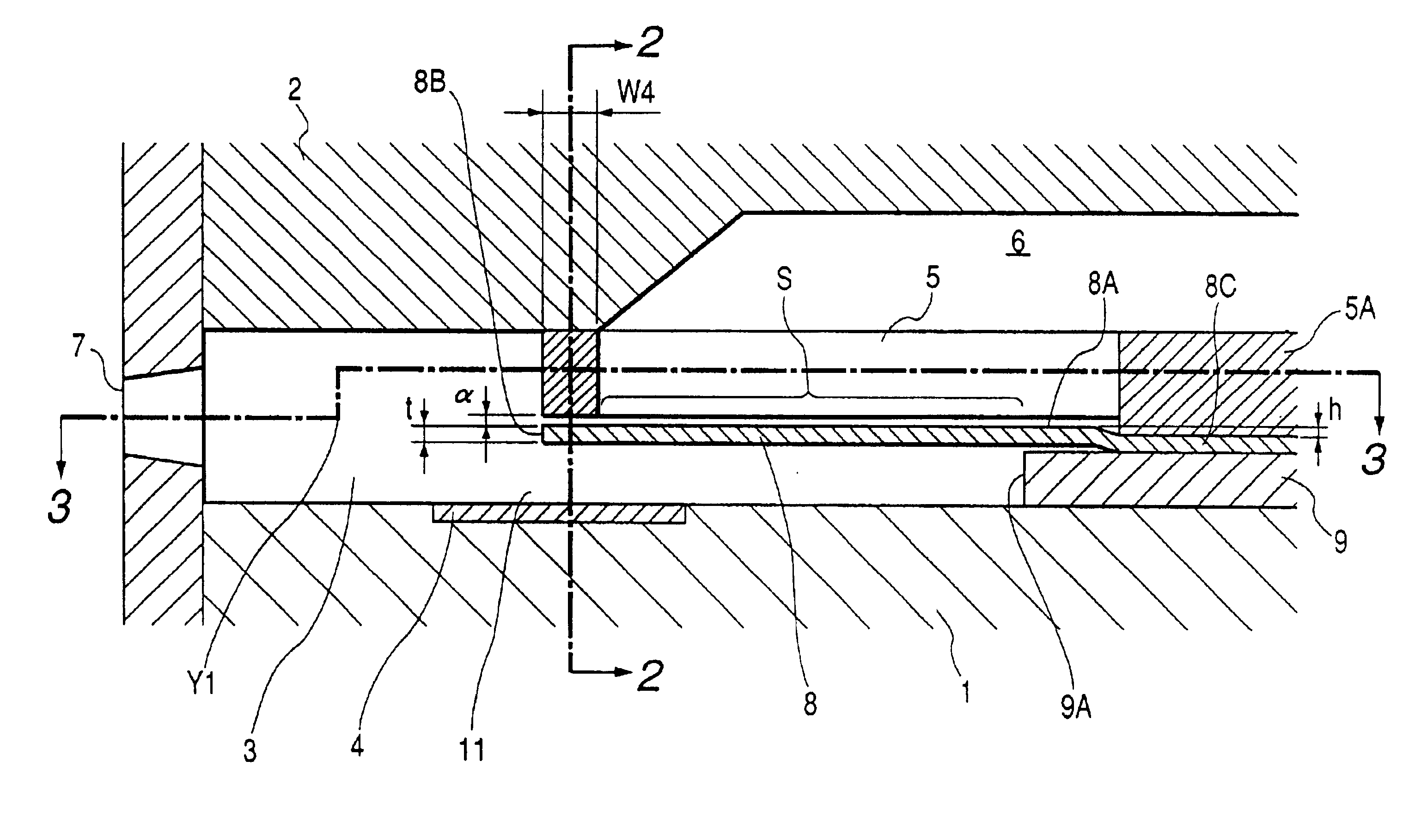
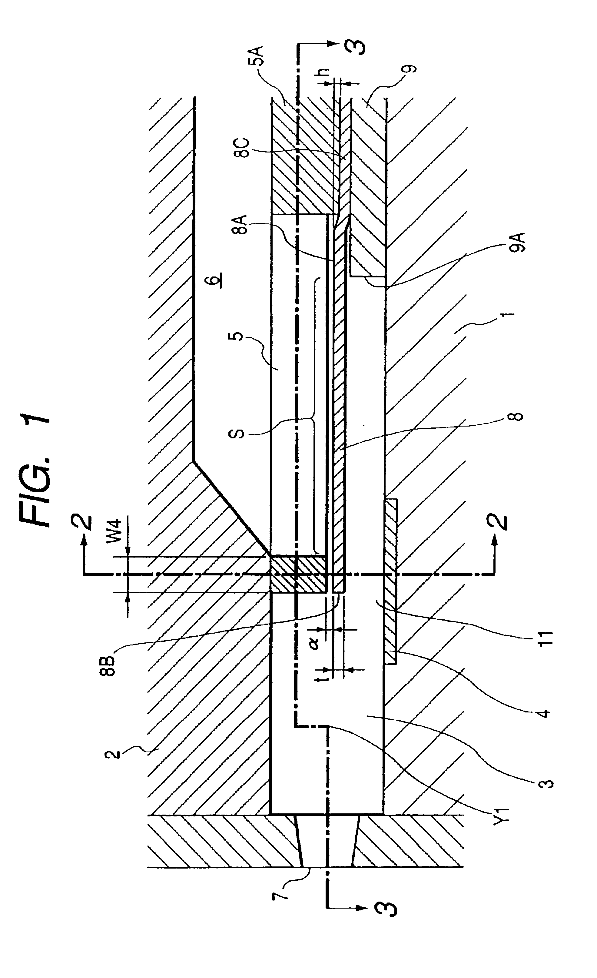
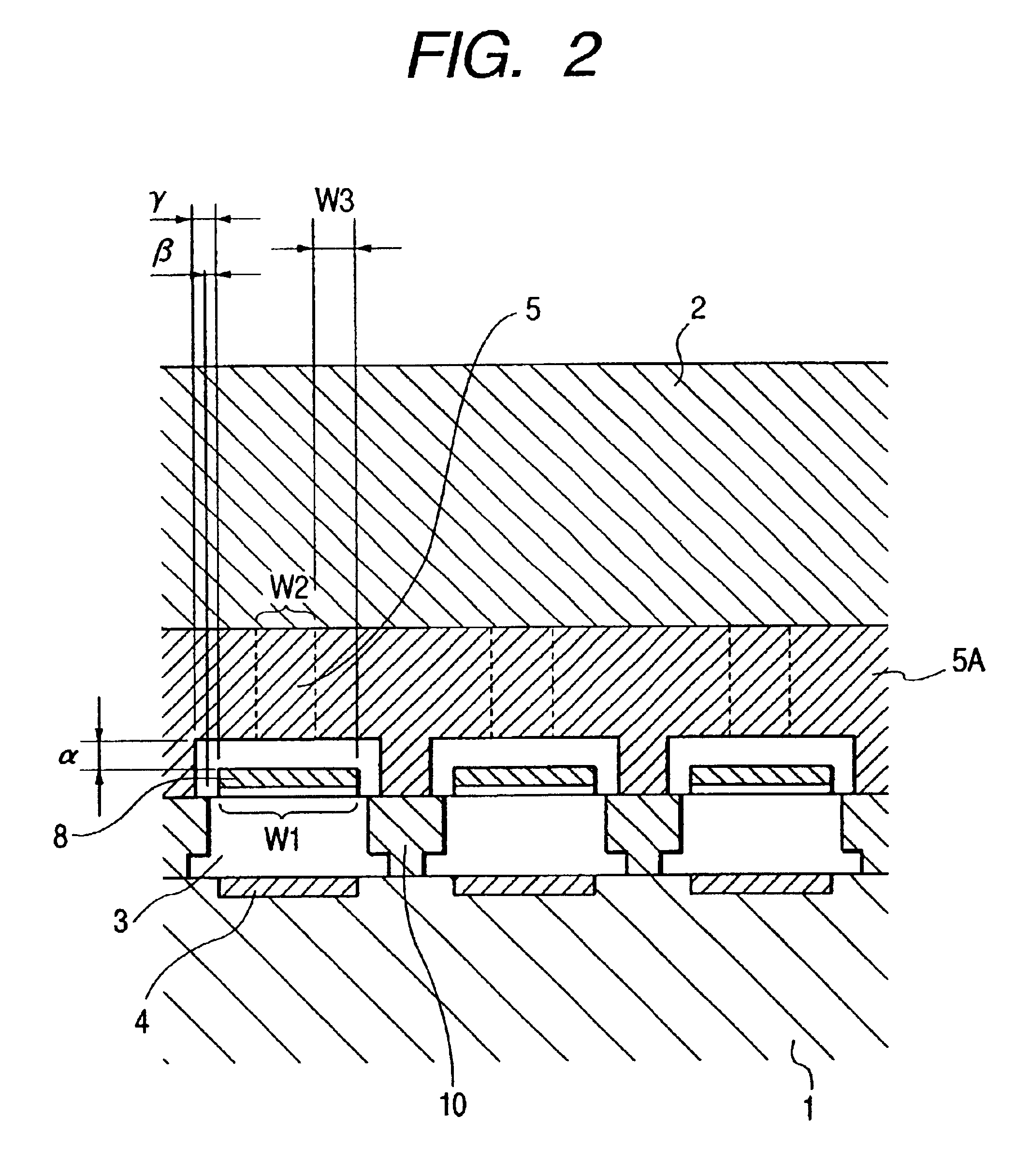
FIG. 1 is a cross-sectional view which shows a liquid discharge head in accordance with a first embodiment of the present invention, taken in the direction of one liquid flow path. FIG. 2 is a cross-sectional view taken along line 2—2 in FIG. 1. FIG. 3 is a cross-sectional view taken along line 3—3 in FIG. 1, which shows a shift from the center of the discharge port to the ceiling plate 2 side at a pint Y1.

For the liquid discharge head shown in FIG. 1 to FIG. 3, which is in the mode of plural liquid paths—a common liquid chamber, the elemental base plate 1 and the ceiling plate 2 are fixed in a state of being laminated through the liquid path side walls 10. Then, between both plates 1 and 2, a liquid flow path 3 is formed, one end of which is communicated with the discharge port 7. This flow path 3 is arranged in plural numbers for one head. Also, on the elemental base plate 1, there is arranged for each of the liquid flow paths 3, the heat generating element 4, su...

second embodiment

(Second Embodiment)

For the head structure of the first embodiment, the position of the foot supporting member 8C of the movable member 8, which is not to be in contact with the fixing member 9 (that is, bent to rise) as shown in FIGS. 1 to 3, is not the same as the edge portion 9A of the fixing member 9. Therefore, the opening area S becomes the area surrounded by the three sides of the liquid supply port 5 and the edge portion 9A of the fixing member 9. However, as shown in FIGS. 12, 13, it may be possible to adopt a mode in which the position of the foot supporting member 8C of the movable member 8 being bent to rise from the fixing member 9 is set at the edge portion 9A of the fixing member 9. In the case of this mode, the opening area S becomes the area surrounded by the three sides of the liquid supply port 5 and the fulcrum 8A of the movable member 8 as shown in FIGS. 12 and 13.

Also, as shown in FIG. 3, the liquid supply port 5 is arranged to be an opening surrounded by four w...

third embodiment

(Third Embodiment)

Further, for each of the embodiments described above, it is more preferable to make the thickness t of the movable member 8 larger than the stepping amount h of the foot supporting member 8C of the movable member 8 as shown in FIGS. 1, 12, or FIG. 14, for example. Here, it is arranged to set the t=5 μm, and the h=2 μm, for example. With this arrangement, it becomes possible to relax the stress concentration which is concentrated on the stepping portion of the foot supporting member 8C of the movable member 8 when the movable member 8 is displaced, hence improving the durability of the foot portion of the movable member 8.

Also, FIG. 16 is an enlarged sectional view which shows the circumference of the foot portion of the movable member in accordance with the head structure represented in FIG. 12. FIG. 17 shows the variational example of the one shown in FIG. 16.

As represented in FIG. 16, the height position of the movable member 8 for each of the embodiments describ...


PUM


Abstract

A liquid discharging method for a liquid head discharge head, which is provided with a plurality of discharge ports for discharging liquid, a plurality of liquid flow paths communicated always with each of the discharge ports at one end, each having bubble generating area for creating bubble in liquid, bubble generating means for generating energy to create and grow the bubble, a plurality of liquid supply ports each arranged for each of the liquid flow paths to be communicated with common liquid supply chamber, and movable member supported with minute gap to the liquid supply port on the liquid flow path side, and provided with free end, the area of the movable member surrounded at least by the free end portion and both sides continued therefrom being made larger than the opening area of the liquid supply port facing the liquid flow path, comprises the step of setting a period for the movable member to close and essentially cut off the opening area during the period from the application of driving voltage to the bubble generating means to the substantial termination of isotropical growth of the entire bubble by the bubble generating means, hence making it possible to enhance the suppressing efficiency of the bubble growing component in the direction opposite to the discharge port, and the refilling characteristics of liquid simultaneously.

Description

BACKGROUND OF THE INVENTION1. Field of the InventionThe present invention relates to a liquid discharge head for discharging liquid by creating a bubble (bubbles) with thermal energy acting upon liquid, and the method of manufacture therefor. The invention also relates to a liquid discharge apparatus that uses such liquid charge head.Also, the present invention is applicable to a printer that records on a recording medium, such as paper, thread, fabric, cloth, leather, metal, plastic, glass, wood, ceramic, a copying machine, a facsimile equipments provided with communication system, and a word processor having a printing unit therefor. The invention further relates to an industrial recording apparatus formed complexly in combination with various processing apparatuses.In this respect, the term “recording” referred to in the specification of the invention hereof not only means the provision of characters, graphics, and other meaningful images for a recording medium, but also, means t...

Claims


Application Information

Patent Timeline
IPC IPC(8): B41J2/14B41J2/16B41J2/005
CPCB41J2/14048B41J2/1604B41J2/1623B41J2/1628B41J2/1646B41J2/1631B41J2/1642B41J2/1645B41J2/1629B41J2/005
Inventor KUBOTA, MASAHIKOSUGITANI, HIROSHITAKENOUCHI, MASANORIIKEDA, MASAMIKUDO, KIYOMITSUINOUE, RYOJISAITO, TAKASHI
Owner CANON KK
Why Eureka
Try Eureka