Dual magnification reversible spot mirror releasably attachable to flat surfaces

a mirror and spot mirror technology, applied in the field of mirrors, can solve the problems of inconvenient positioning of the face sufficiently close to the existing flat mirror, and the general degeneration of the person's vision with age, and achieve the effect of greater magnification

Active Publication Date: 2005-02-15
ZADRO INC
View PDF13 Cites 24 Cited by
  • Summary
  • Abstract
  • Description
  • Claims
  • Application Information

AI Technical Summary

Benefits of technology

To remove the mounting bracket, the mirror frame holder is moved parallel to a mounting surface to thereby position a suction cup head beneath the larger diameter, circular portion of a keyhole, and the bracket plate pulled forwards away from the mounting surface, the larger diameter circular portions of the keyholes enabling the suction cup heads to be pulled through the keyholes. The suction cups are then individually removed from hermetic contact with the mounting surface. Optionally, each suction cup is provided with a small lifting tab which protrudes radially outwards from a lower peripheral edge of the surface-contacting edge wall of the suction cup. Grasping this tab and pulling it away from a surface to which the suction cup is hermetically adhered breaks the hermetic seal between the surface and the suction cup, enabling the suction cup to be easily detached from a mounting surface.
In the preferred embodiment of a dual magnification reversible mirror device according to the present invention, the mounting bracket plate is vertically elongated, and is provided at an upper end thereof with a pair of laterally spaced apart, horizontally outwardly protruding pivot pins which fit within a pair of opposed, laterally disposed and aligned tubular bushings that protrude rearwardly from the rear of the circular mirror frame holder base, near an upper peripheral edge of the vertical, upright portion of the cross-shaped back wall of the frame holder. With this construction, the mirror frame is pivotably adjustable from an orientation parallel to the vertical surface of a larger mirror or other such mounting surface, to a desired upwardly angled inclination. Thus, the dual magnification reversible mirror device according to the present invention provides a smaller, “spot” image of selectably greater magnification than a larger flat mirror to which the device is releasably mounted. Preferably, the frame holder base has through its thickness dimension a plurality of clearance holes which are aligned with the mounting bracket suction cups. The clearance holes are provided to receive the heads of the suction cups, thus enabling the mirror frame holder to be pivoted into a flush, overlying relationship with the mounting bracket plate.

Problems solved by technology

In some circumstances, however, it is not convenient to position one's face sufficiently close to an existing flat mirror to provide an image of the face which is sufficiently large to enable a desired personal grooming task to be easily performed.
However, since a person's vision generally degrades with age, there is an accompanying need for a small, “spot” mirror of selectable magnification which can be attached to an existing larger mirror to enable a person to see image details required to perform personal care functions.

Method used


Image

  • Dual magnification reversible spot mirror releasably attachable to flat surfaces
  • Dual magnification reversible spot mirror releasably attachable to flat surfaces
  • Dual magnification reversible spot mirror releasably attachable to flat surfaces

Examples


Embodiment Construction

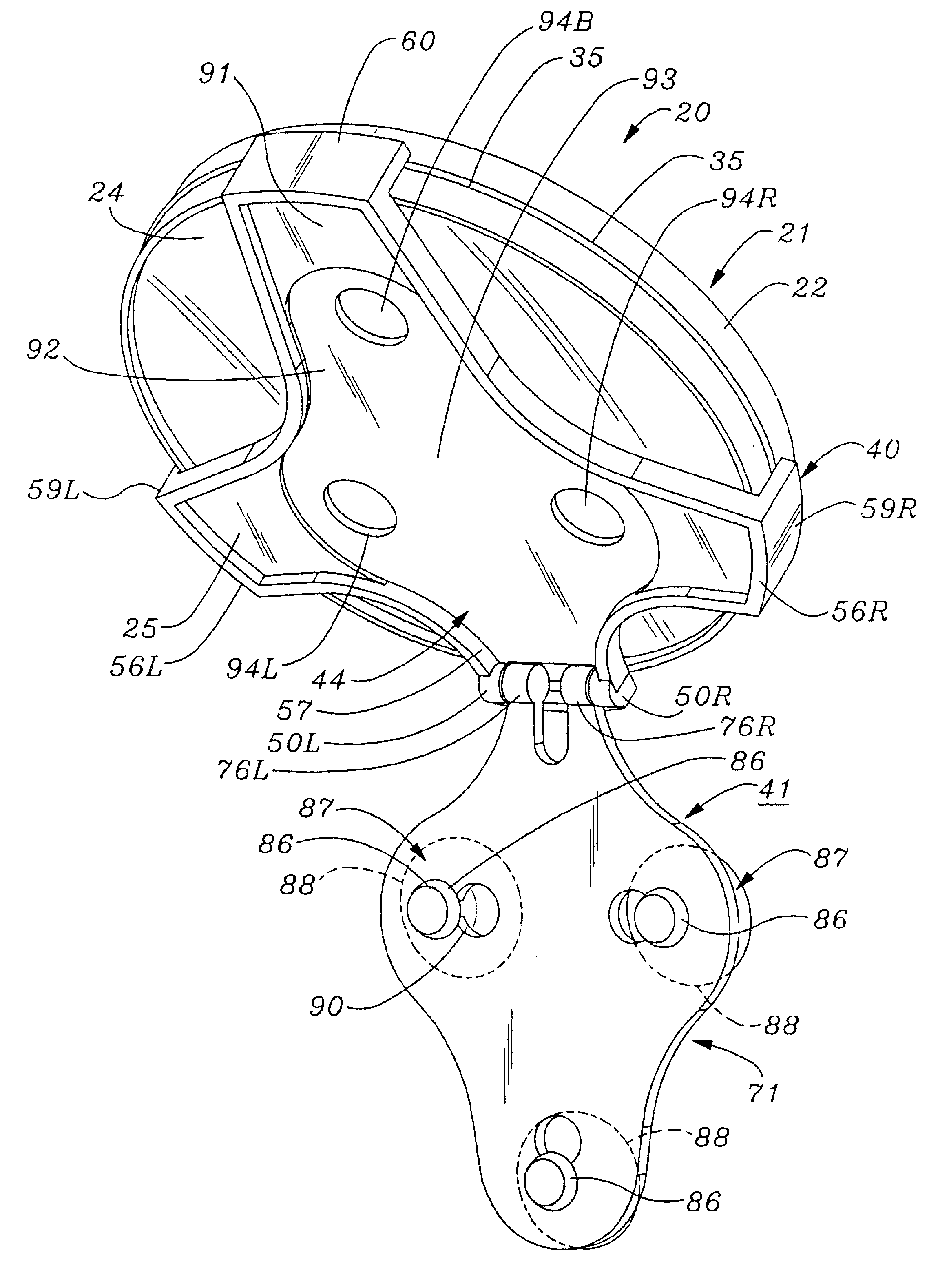
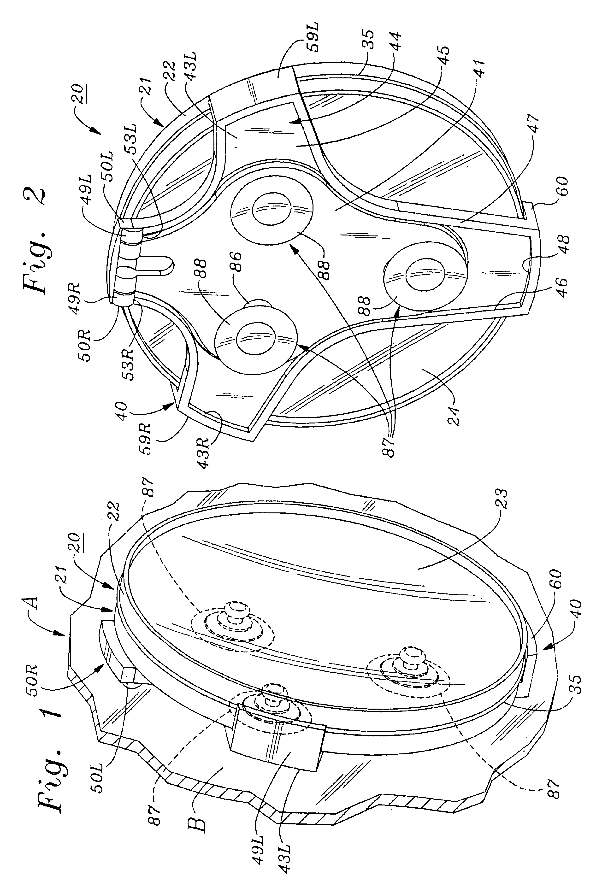
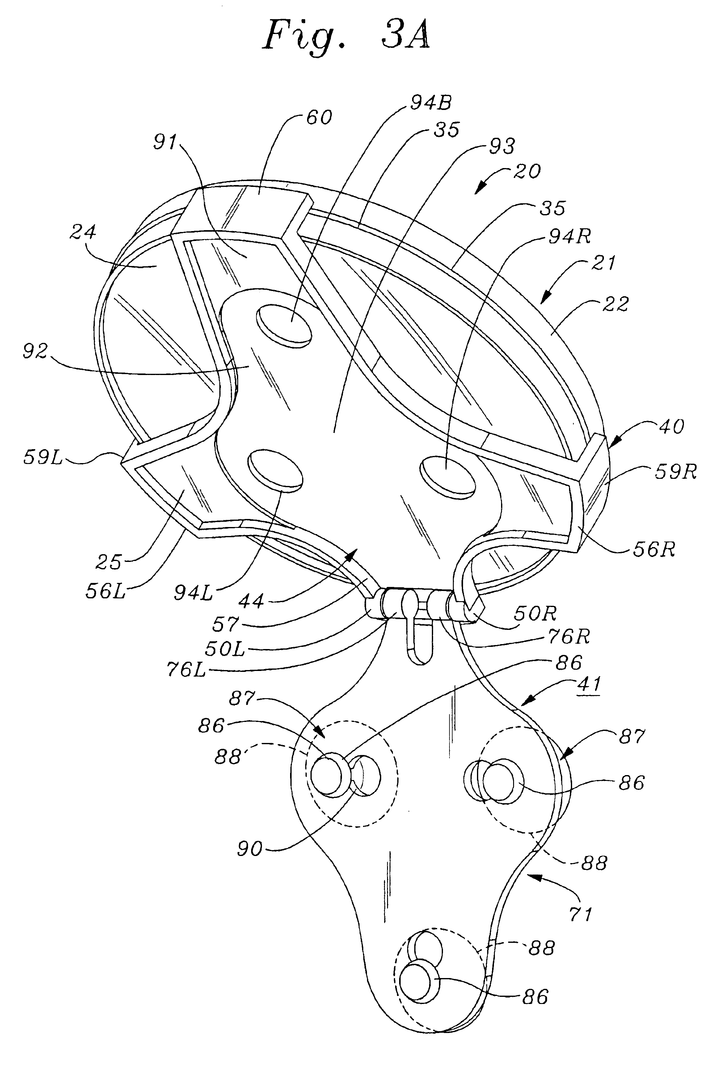
FIGS. 1-10 illustrate various structural and functional aspects of a dual magnification, reversible spot mirror according to the present invention.

As shown in FIGS. 1-3B, a dual magnification reversible mirror 20 according to the present invention includes a dual mirror frame assembly 21 that contains within a circular ring-shaped frame hoop 22 a pair of circular mirror plates 23, 24. As may be seen best by referring to FIG. 9 in addition to FIGS. 1-3B, mirror plates 23, 24 have concave, spherically curved reflective surfaces 25, 26 of different curvature. Thus, mirror plates 23, 24 have different magnifications, e.g., 5× and 10×.

As shown in FIG. 9, mirror plates 23, 24 have convexly curved rear surfaces 27, 28. Also, mirror frame hoop 22 has formed in an inner cylindrical wall surface 29 thereof front and rear counterbore entrance openings 30F, 30R which form front and rear annular ring-shaped shoulder ledges 31F, 31R, respectively, that support the outer peripheral edges of rear s...


PUM


Abstract

A dual magnification reversible spot mirror device includes two mirrors having different magnifications, e.g., 5X and 10X, mounted back-to-back in a cylindrical frame ring which has an outer cylindrical wall surface from which protrudes a circumferential annular ring-shaped rib, and a mirror frame holder which has protruding forwardly from a base thereof a plurality of circumferentially spaced apart, longitudinally disposed flange walls which are elastically deformable in a radially outwardly direction from a longitudinal center line perpendicular to the base. Retainer lips protruding radially inwardly from inner longitudinal wall surfaces of the flange walls are forced radially outwardly in response to rearward forcible contact with the lips by the frame rib, whereupon the flange walls deflect elastically inwardly to an undeformed position in which the mirror frame ring with a reversible selected mirror facing outwards is captivated between a front wall surface of the base and rear surfaces of the flange wall lips. The base of the mirror frame holder is pivotably mounted to a mounting base which has suction cups protruding rearwardly therefrom for releasable attachment to a flat surface such as the vertical surface of a larger wall or cabinet mirror, or the horizontal surface of a table top or vanity.

Description

BACKGROUND OF THE INVENTIONA. Field of the InventionThe present invention relates to mirrors of the type used by people to facilitate performance of personal care functions such as shaving, applying cosmetics, and the like. More particularly, the invention relates to a novel mirror device which includes a mirror frame assembly in which is mounted a pair of back-to-back mirror plates of different relative magnification, a mirror frame support assembly into which the mirror frame assembly is reversibly installable with a mirror plate of selected magnification facing outwardly, and a mounting base which is releasably attachable to a flat surface such as that of a large flat mirror or table top, with the mirror positioned at an adjustable inclination angle relative to the mounting surface.B. Description of Background ArtSome aspects of a person's appearance are best attended to by observing his or her image in a relatively large “wide angle” mirror, which has unity or “1×” magnification...

Claims


Application Information

Patent Timeline
Patent Type & Authority Patents(United States)
IPC IPC(8): A45D42/00A45D42/14
CPCA45D42/14
Inventor ZADRO, ZLATKO
Owner ZADRO INC
Why Eureka
Try Eureka