Window view binder cover

a binder cover and window view technology, applied in the field of improved binder covers, can solve the problems of not providing a satisfactory system for mounting small flat objects, such as photographs, on the cover

Inactive Publication Date: 2005-02-15
ONG BON S
View PDF30 Cites 33 Cited by
  • Summary
  • Abstract
  • Description
  • Claims
  • Application Information

AI Technical Summary

Benefits of technology

The present invention provides a means for suitably mounting flat articles, such as photographs, drawings, and even title sheets, for display at the surface of a hinder cover. Unlike conventional systems, the improved binder cover of the invention provides a means for internally mounting articles for display so that they may be viewed through window openings in the cover. Moreover, a backing sheet located at the inside surface of the binder cover may be delineated into one or more pockets of a desired size so as to hold one or more flat display articles snugly in position so that those articles do not slide around and become crooked relative to the edges of the cover. Quite to the contrary, pockets of a selected size may be defined on the inside surface of the cover so as to snugly receive articles to be displayed therewithin. The displayed articles are held in position on the inside surface of the cover, but are visible through window openings in the cover.

Problems solved by technology

While such externally mounted jackets do provide a suitable display pocket for flat articles of a size that approaches the size of the cover, such a system does not provide a satisfactory system for mounting smaller flat articles, such as photographs, on the cover.

Method used


Image

  • Window view binder cover
  • Window view binder cover
  • Window view binder cover

Examples


Embodiment Construction

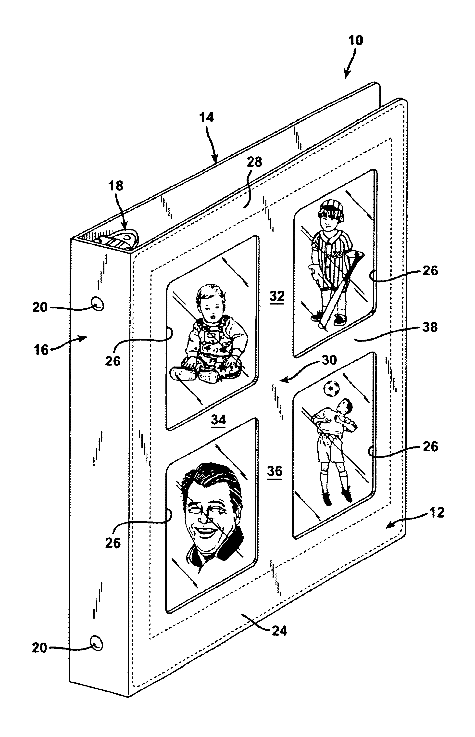
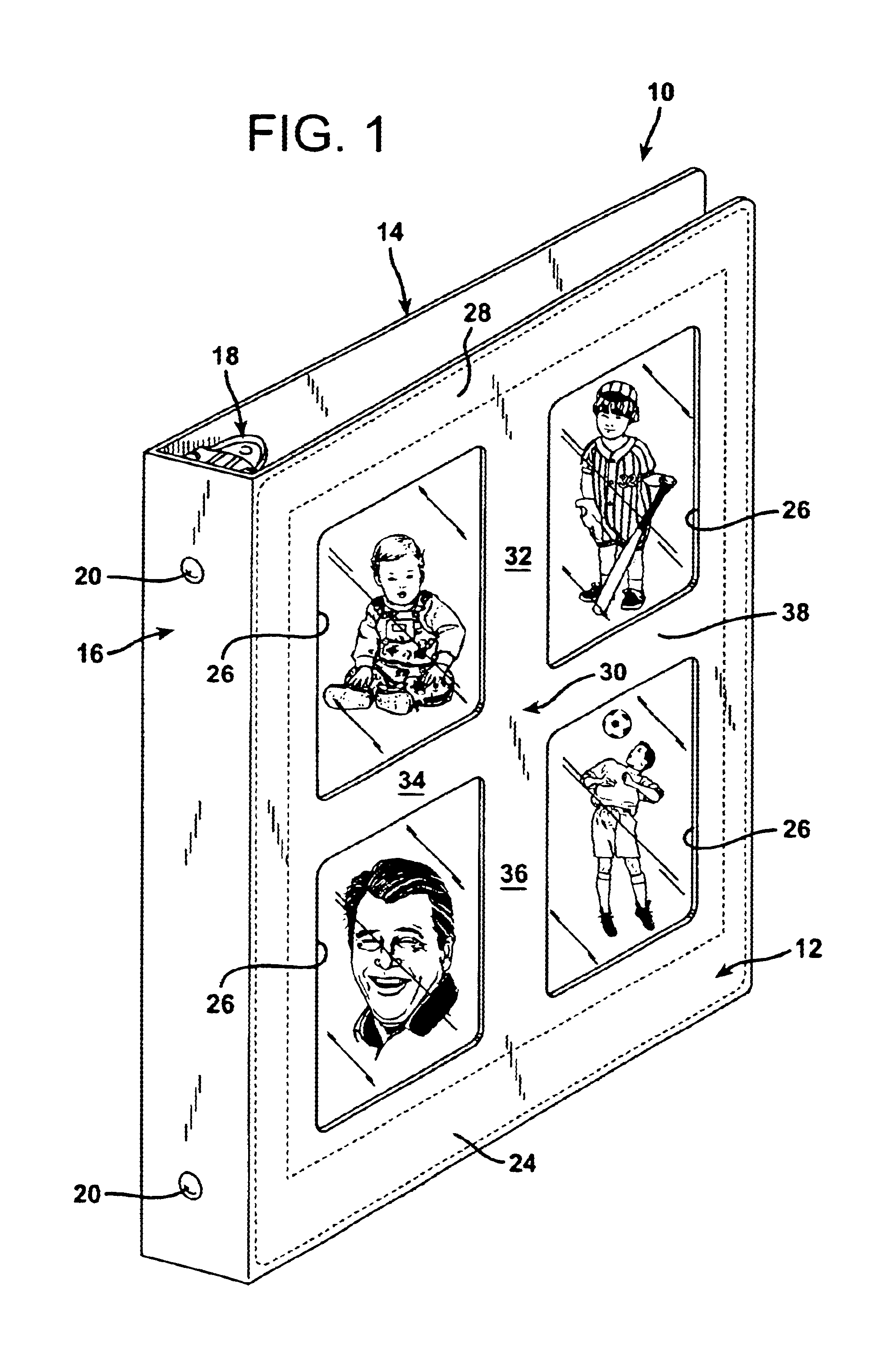
FIG. 1 illustrates a three-ring notebook binder 10 including a front cover 12, a back cover 14, and a spine panel 16. The three-ring binder 10 includes a conventional three-ring gripping assembly 18 located on the inside surface of the spine panel 16 and secured thereto by rivets 20.

The front cover 12, spine panel 16, and rear cover 14 may all be formed of a unitary sheet of stiff polypropylene or polyvinyl chloride scored longitudinally to delineate the demarcations between the front cover 12 and spine panel 16 and between the spine panel 16 and the back cover 14. The covers 12 and 14 of the binder 10 may be folded together to close the binder 10, as illustrated in FIG. 1, or opened to allow the contents of the binder 10 to be displayed, as illustrated in FIG. 3.

The front cover 12 has an inside hidden surface 22, visible in FIG. 2, and an outside, exposed surface 24, visible in FIG. 1. At least one, and preferably a plurality of, window openings are defined within the front binder ...


PUM


Abstract

A binder for papers, photographs, or other sheet-like materials is provided with a cover having one or more window openings defined therein. A flat, transparent protective sheet is located in contact with the inside surface of the binder cover and a backing sheet overlies the protective sheet. The backing sheet is secured to the peripheral margin of the protective sheet, and elsewhere as required, to delineate at least one, and preferably a plurality of pockets. The pockets are formed between the backing sheet and the protective sheet. An elongated slit in defined through the backing sheet behind each pocket created. The peripheral edges of the backing sheet are permanently secured to the inside surface of the binder cover. Photographs or other flat display materials may be inserted into the pockets formed between the backing sheet and the protective sheet through the elongated slits. The pockets are delineated so that they are aligned with the window opening in the cover. The photographs or other display materials may thereby be viewed through the window openings from the outside through the transparent protective sheet. Selected display materials may be inserted and withdrawn from the pockets through the elongated slits in the backing cover.

Description

BACKGROUND OF THE INVENTION1. Field of the InventionThe present invention relates to an improved binder cover which permits photographs, drawings, and other flat display articles to be mounted at window openings in a binder cover and supported from behind.2. Description of the Prior ArtVarious types of systems have been devised for mounting flat articles to be displayed in the covers of binders that are used for holding various sheets of paper and other flat materials. For example, some binder covers are equipped with transparent jackets located on their outer surfaces and which are secured to the outer surfaces of the binder covers to form exterior pockets. The transparent sheet of envelope material is generally left unsecured along one edge so that flat sheets to be displayed may be inserted in between the externally mounted jacket and the binder cover.While such externally mounted jackets do provide a suitable display pocket for flat articles of a size that approaches the size of...

Claims


Application Information

Patent Timeline
Patent Type & Authority Patents(United States)
IPC IPC(8): B42F13/00
CPCB42F13/0013
Inventor ONG, BON S.
Owner ONG BON S
Why Eureka
Try Eureka