Electronic trigger pull gauge

a trigger pull gauge and electronic technology, applied in the direction of instruments, force/torque/work measurement, explosion force measurement, etc., can solve the problems of affecting the accuracy of the system is limited, and the known trigger pull gauge suffers. , to achieve the effect of simple operation and accurate results

Inactive Publication Date: 2005-02-15
LYMAN PRODS CORP
View PDF8 Cites 81 Cited by
  • Summary
  • Abstract
  • Description
  • Claims
  • Application Information

AI Technical Summary

Benefits of technology

[0008]Accordingly, it is an object of the present invention to provide a gauge for measuring the force required to discharge a firearm by pulling its trigger which is simple to operate and produces accurate results.

Problems solved by technology

These known trigger pull gauges, however, suffer from a number of disadvantages.
One such disadvantage is that they require the user to continuously monitor the position of an indicator or slide along a series of metered markings and to determine the position of the indicator or slide at the point where the trigger releases the firing mechanism.
This may lead to inaccurate results or require that the test be repeated if the user is not paying extremely close attention.
Another disadvantage is that the precision of the system is limited by the users ability to discern slight movements of the indicator or slide along the metered markings.
As such, system resolution may be poor.
A further disadvantage of these systems is that they are cumbersome in that they require the user to perform a number of tasks simultaneously, including holding the gauge and / or firearm, actuate the gauge by either pulling on it or rotating the threaded rod, and carefully monitoring the position of the indicator or slide along the metered markings.
Another disadvantage relates to the fact that the user of the system may desire to perform a number of trigger pull measuring tests and then average the results.
Using known systems, the user would disadvantageously be required to perform each cumbersome test individually and then to manually perform calculations in order to arrive at an average.

Method used


Image

  • Electronic trigger pull gauge
  • Electronic trigger pull gauge
  • Electronic trigger pull gauge

Examples


Embodiment Construction

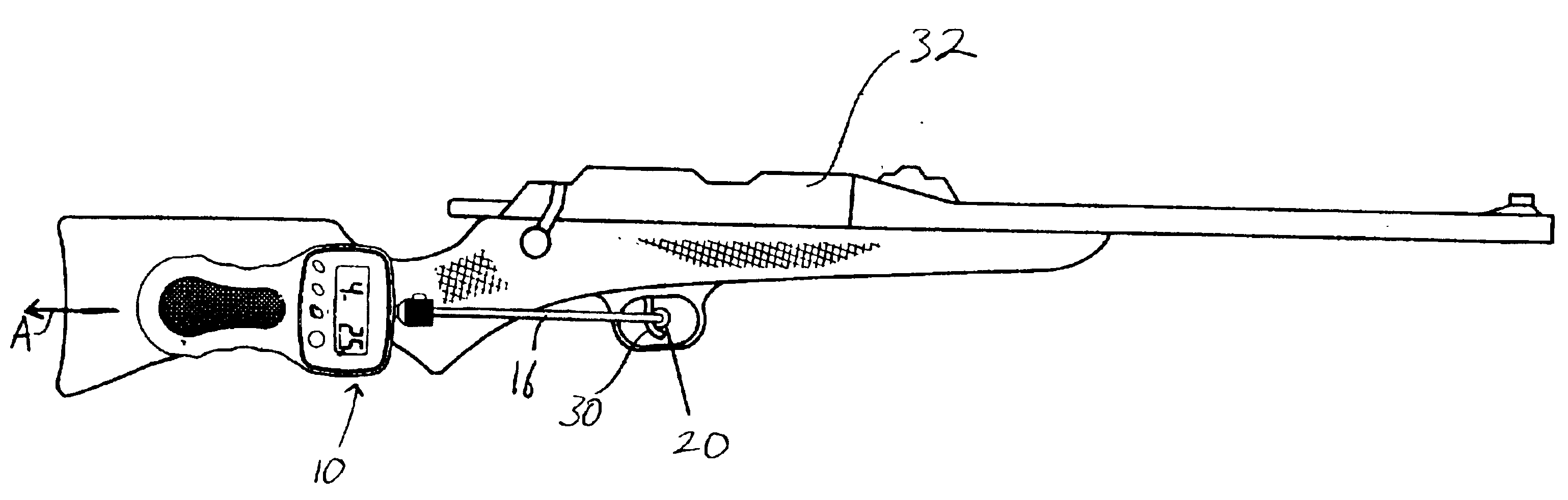
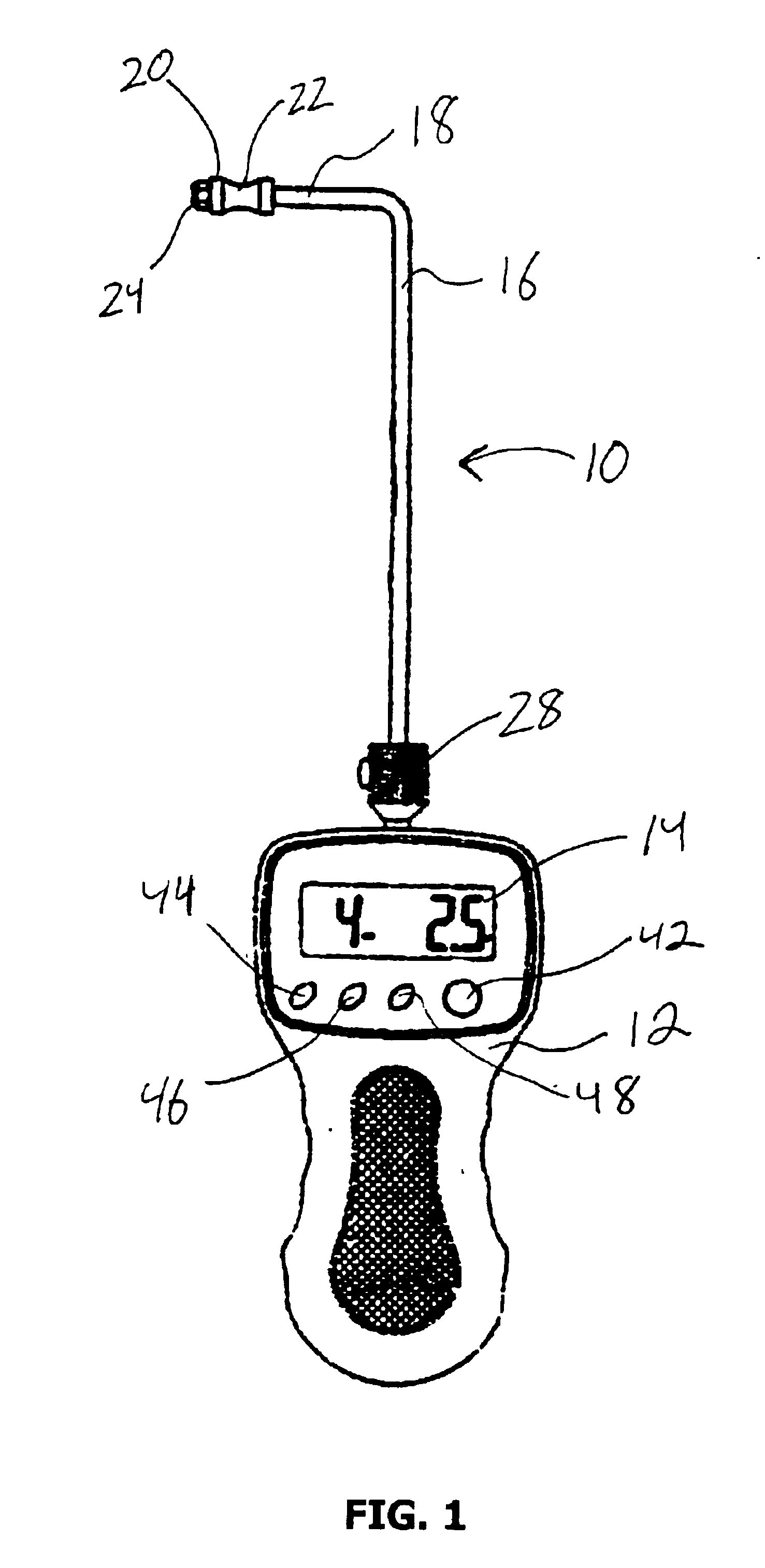
[0021]Referring first FIG. 1 a gauge 10 for measuring the force required to discharge a firearm by pulling its trigger (hereinafter referred to as “trigger pull”) in accordance with the present invention is shown. Gauge 10 includes a housing 12 in which the device's electronics (described more fully below) are contained and an LCD display 14 for communicating test results and other information to the user. Gauge 10 also includes a rod 16 extending therefrom which includes a trigger hook portion 18 at a distal end thereof. Trigger hook portion 18 preferably includes a trigger roller 20 rotatably mounted thereon to facilitate engagement with a trigger of a firearm whose trigger pull is to be measured.

[0022]Trigger roller 20 is preferably cylindrical in shape with a recessed groove 22 around its periphery which allows trigger roller to be seated on a trigger without easily slipping off during testing. The rotatability of trigger roller 20 reduces friction between trigger hook portion 1...


PUM


Abstract

A gauge for measuring the force required to discharge a firearm by pulling its trigger includes a housing and a rod including a trigger hook portion at a distal end thereof for engaging the trigger. A load cell is connected to the housing and to a proximal end of the rod such that the load cell generates an electrical signal in response to forces on the rod as the housing is pulled while the trigger hook portion is engaged with the trigger. The magnitude of the electrical signal is proportional to the forces on the rod. A microcontroller receives the electrical signal and calculates a force value based thereon. The microcontroller also continuously monitors the forces on the rod and identifies a trigger pull value of the firearm as being the maximum force on the rod until pulling on the housing is ceased once the trigger of firearm has released.

Description

FIELD OF THE INVENTION[0002]The present invention relates generally to a measuring device for use with firearms, and more particularly to an electronic gauge for measuring the force required to discharge a firearm by pulling its trigger.BACKGROUND OF THE INVENTION[0003]It is often important to be able to measure the force required to discharge a firearm by pulling its trigger (hereinafter referred to as “trigger pull”). Measuring the trigger pull of a firearm is most often necessary in conjunction with adjusting the trigger pull to reach a desired value. For example, one might desire to assure that the trigger pull of a firearm meets the manufacturer's specifications for that particular firearm. In another example, one might desire to adjust all of his or her firearms to have the same trigger pull so that discharge of the firearms during use can be better anticipated.[0004]Various devices for measuring a firearm's trigger pull are known. Such devices have traditionally employed scal...

Claims


Application Information

Patent Timeline
Patent Type & Authority Patents(United States)
IPC IPC(8): F41A31/00
CPCF41A31/00
Inventor RANZINGER, RICHARD
Owner LYMAN PRODS CORP
Why Eureka
Try Eureka