Capsule endoscope

a technology of endoscope and capsule, which is applied in the field of capsule endoscope, can solve the problems of degrading the image detected by the image pickup, difficult observation and diagnosis, and high probability

Inactive Publication Date: 2005-02-15
OLYMPUS CORP
View PDF8 Cites 94 Cited by
  • Summary
  • Abstract
  • Description
  • Claims
  • Application Information

AI Technical Summary

Benefits of technology

The present invention relates to a capsule endoscope which is to be swallowed in order to inspect portions of the interior of a living body, and enables an object that is located within the depth of field of an objective optical system of the capsule endoscope to be illuminated with a nearly uniform illumination distribution. Furthermore, the present invention provides a capsule endoscope that prevents dust, such as shaving dregs of a lens frame that may be produced in performing a focus adjustment, from attaching to the front side of the image pickup and degrading the detected image.

Problems solved by technology

When multiple light emitting elements are arranged at the periphery of an objective optical system, as in the above-mentioned patent publication, observation and diagnosis are made difficult if there exists any offset or change in the illumination onto an irradiated surface.
Furthermore, dust or particles such as shaving dregs created when a lens frame is moved when performing an initial focus adjustment of the objective optical system can easily settle on the image surface of the image pickup, causing the likelihood to be too high that images detected by the image pickup will be degraded.

Method used


Image

  • Capsule endoscope
  • Capsule endoscope
  • Capsule endoscope

Examples


embodiment 1

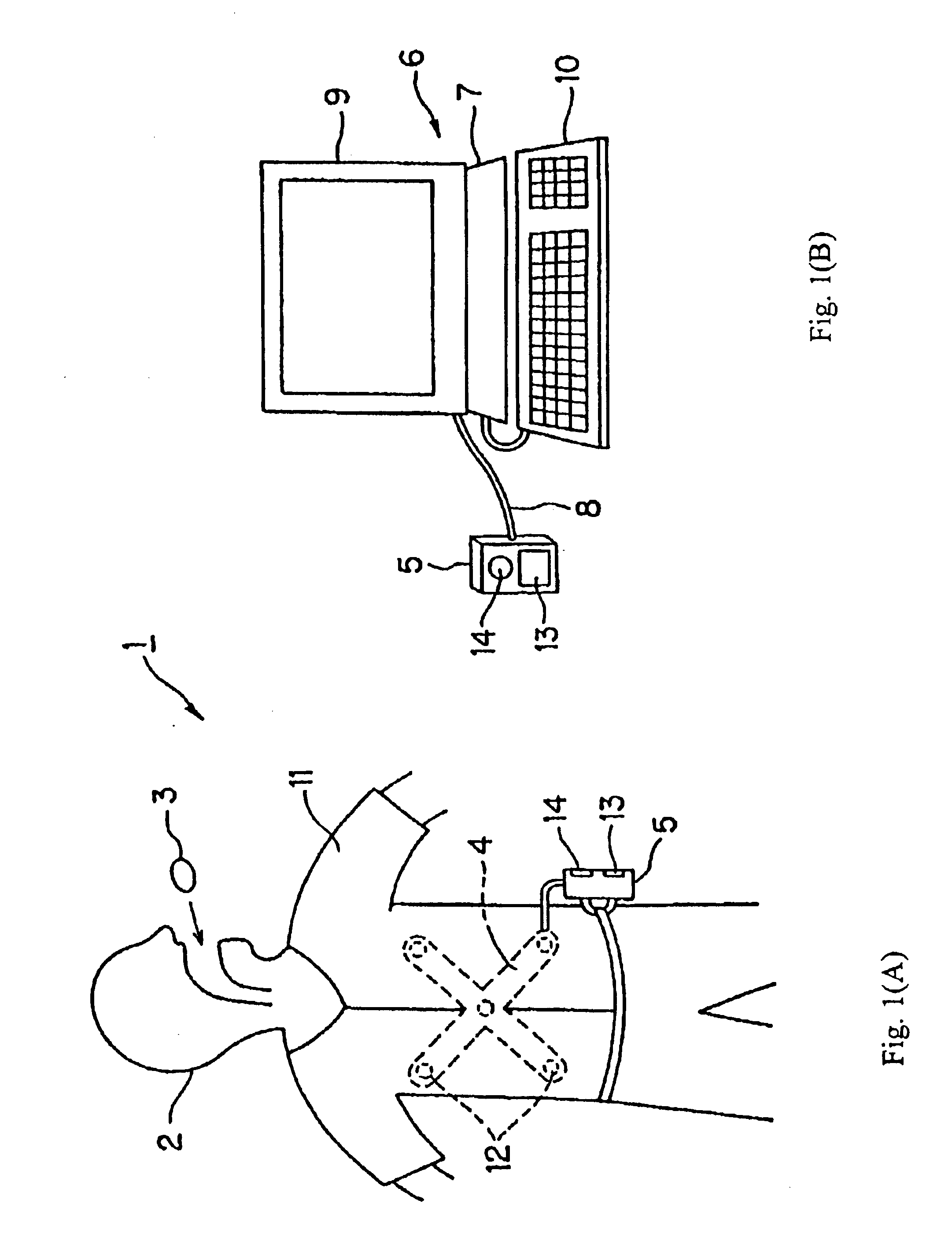
This embodiment will be discussed with reference to FIGS. 1(A)-6(B). As shown in FIG. 1(A), a capsule endoscope system 1 employs a capsule endoscope 3 which transmits an image signal that is obtained by optically imaging an inner surface of a coelomic canal, detecting the image with an image detecting element, wirelessly transmitting the detected image signal to an external unit 5 which receives, via an antenna unit 4, electromagnetic signals transmitted by the capsule endoscope 3. The antenna unit 4 is provided outside the body of a patient 2, and the external unit functions to temporarily store the image information that is received using, for example, a hard disc of compact flash (R) size having a memory capacity of, for example, 1 GB.

As shown in FIG. 1(B), the external unit 5 may be detachably connected via a communication cable, such as USB cable 8, to a personal computer (hereinafter PC) 7. Image data accumulated in the external unit 5 can be transferred to a display system 6 ...

embodiment 2

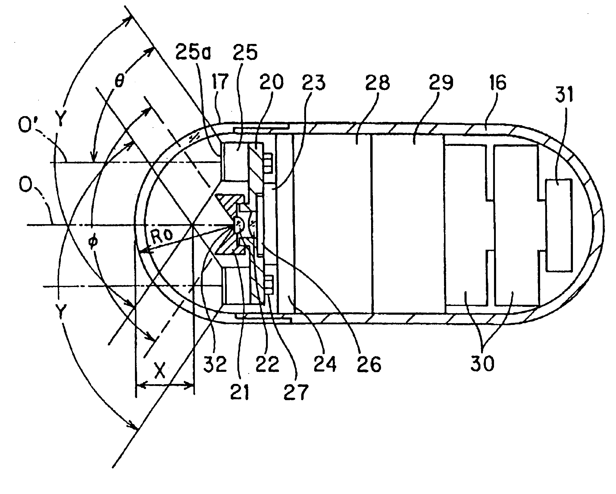
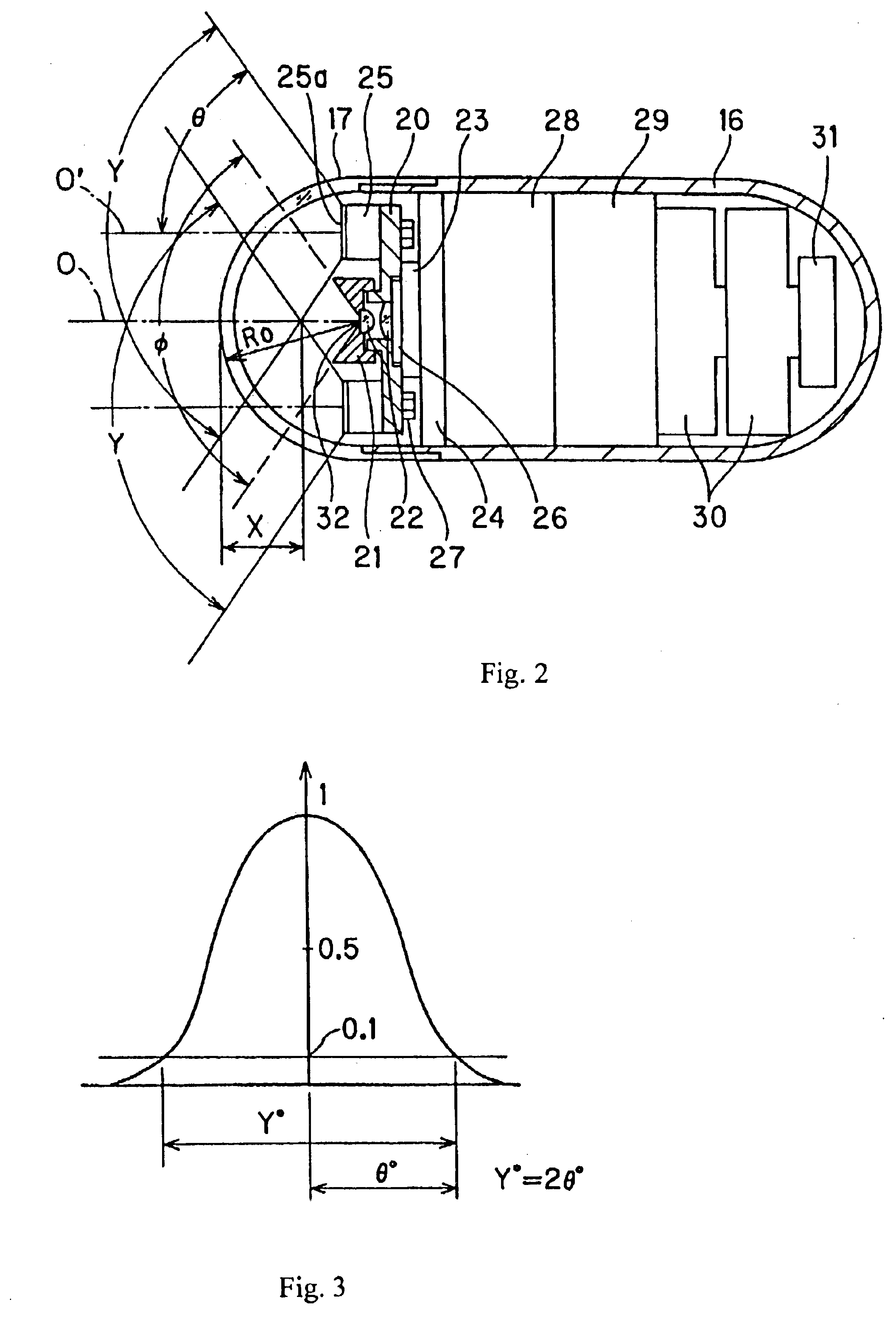
FIG. 7 illustrates Embodiment 2 of the present invention. In the capsule endoscope 41 of Embodiment 2, just as in Embodiment 1, a semi-spherical transparent cover 17 is connected to the front end of a cylindrical outer case 16 so as to be water-tight. The rear end of the cylindrical outer case 16 has a rounded shape and the following components are accommodated within the closed capsule. A lens frame 43 is fitted with a first lens, in order from the object side, of an objective optical system 42. The lens frame 43 is mounted about the center axis O of the cylindrical outer case 16 by fitting it within a central bore of a sealing cover 44 which serves as a lens frame for mounting the second lens, in order from the object side, of the objective optical system 42. At the image position of the objective optical system 42, a CMOS image pickup device 23 is mounted to the front side of a substrate 24. The surface of the image pickup device 23 is protected by the sealing cover 44 and the se...

embodiment 3

FIG. 8 illustrates Embodiment 3 of the present invention. Like the capsule endoscope 41 shown in FIG. 7, the capsule endoscope 51 of Embodiment 3 has a semi-spherical transparent cover 17 that is connected and sealed in a water-tight manner to the front end of an outer cylindrical case 16. A lens frame 54 that is fitted with a first lens 53a, in order from the object side, of an objective optical system 52 is focused and then fixed to the second lens 53b of the objective optical system 52. A second lens 53b, in order from the object side, of an objective optical system 52 is mounted to a cover glass 55 which covers a CMOS image pickup device 23 that is mounted to the front surface of a substrate 24.

More specifically, the second lens 53b is cemented using a transparent adhesive, or the like, and is fixed to the front surface of a cover glass 55 mounted so as to protect the image sensor surface of the CMOS image pickup device 23. The lens frame 54 has an inner diameter that is attache...


PUM


Abstract

A capsule endoscope is provided with lighting means for illuminating the interior of a living body, an image pickup means for capturing an image of a site illuminated by the lighting means, and a transparent cover which houses the image pickup means and the lighting means within a sealed, cylindrical-shaped capsule case. The image pickup means includes an objective optical system having a depth of field. An object within the depth of field of the objective optical system is illuminated more evenly than possible with a single lighting means by arranging multiple lighting means at the periphery of the objective optical system and causing the beams from individual lighting means to overlap in specified ways so that a nearly uniform illumination of an object of interest is achieved. Light diffusers may be employed to diffuse the light from the light sources, and a color correction filter may be used.

Description

BACKGROUND OF THE INVENTIONRecently, endoscopes have found wide use in medical fields and in industry. More recently, the pain that is normally associated with the use of an endoscope has been eliminated for some endoscope applications by the development of a capsule endoscope. Japanese Laid-Open Patent Application 2001-91860 is one example of such an endoscope, wherein an objective optical system, image pickup, and light source are contained within a capsule that is swallowed by a patient. The light source employs light emitting elements that are symmetrically arranged within a nearly semi-spherical transparent cover, and objects that are positioned within an observation range illuminated by the light emitting elements are imaged by the objective optical system onto the image pickup.In the above-mentioned patent publication, an objective lens system and two illuminators are fixed inside the nearly semi-spherical transparent cover, and a lens barrel which supports the objective lens...

Claims


Application Information

Patent Timeline
Patent Type & Authority Patents(United States)
IPC IPC(8): A61B1/06G02B23/24A61B1/00H04N5/225
CPCA61B1/041A61B1/0684A61B1/0607
Inventor YOKOI, TAKESHIHASEGAWA, AKIRAMATSUMOTO, SHINYASUZUKI, TAKAYUKISEGAWA, HIDETAKETAKIZAWA, HIRONOBU
Owner OLYMPUS CORP
Why Eureka
Try Eureka