Catheter shaft with coextruded stiffener

a coextruded, catheter technology, applied in the direction of catheters, guide wires, manufacturing tools, etc., can solve the problems of shaft material crumple, manufacturing difficulties, and difficulty, and achieve the effect of resisting socking, maintaining the overall stiffness of the shaft, and varying the flexibility and steerability characteristics of the sha

Inactive Publication Date: 2005-02-15
MYELOTEC CO LTD
View PDF12 Cites 162 Cited by
  • Summary
  • Abstract
  • Description
  • Claims
  • Application Information

AI Technical Summary

Benefits of technology

Briefly described, in its preferred embodiments, the present invention provides a steerable catheter shaft having one or more internal stiffeners coextruded or otherwise formed into the shaft material along a selected portion of the length of the shaft. The stiffener(s) assist in maintaining the overall stiffness of the shaft, and resist socking. Because the stiffener(s) is / are embedded within the body of the shaft, the shaft's exterior can be formed of a softer, atraumatic material. Eccentric placement of the stiffener(s) biases the shaft to steer in an in-plane manner. The configuration of the stiffener(s)—including the size, shape, number and location of the stiffener(s) within the shaft's cross-section and / or along the shaft's length—can be selectively controlled to vary the flexibility and steerability characteristics of the shaft. One or more instrument lumens preferably extend through the catheter shaft for instrument access and / or passage of fluids, medication and the like. One or more steering wires preferably pass through at least a portion of the catheter shaft to effect steering of the shaft. Optionally, the lumen(s) and / or the steering wire(s) pass through the stiffener(s) within the catheter shaft.

Problems solved by technology

A commonly encountered problem in the design of steerable catheters is the provision of acceptable flexibility of the catheter shaft, particularly near the shaft tip, while still maintaining adequate overall shaft stiffness for pushing through tissue openings and other access pathways.
Difficulties are also encountered in providing a desired degree of stiffness to a catheter shaft formed from the relatively softer shaft materials that are often preferred for their trauma minimization qualities.
Another problem suffered by some previously existing catheter shafts is “socking”, wherein the shaft material crumples along the shaft's longitudinal axis when tension is applied to the steering wires, rather than bending along a smooth arcuate path.
For example, some catheter shafts incorporate wire reinforcements encapsulated into their wall material or concentrically coextruded layers, which result in manufacturing difficulties and add considerably to the shaft's expense.
In addition, the inclusion of wire within a catheter shaft may interfere with the guidance and placement of the catheter under flouroscopic observation, or may adversely impact regulatory approvals.
Also, the material dissimilarities between the metal wire and the polymeric catheter shaft may result in slippage therebetween, possibly producing unpredictable steering characteristics.
Welding shaft segments of differing durometer hardness together to form a catheter shaft also requires considerable effort and expense in ensuring proper alignment and connection between the segments.

Method used


Image

  • Catheter shaft with coextruded stiffener
  • Catheter shaft with coextruded stiffener
  • Catheter shaft with coextruded stiffener

Examples


Embodiment Construction

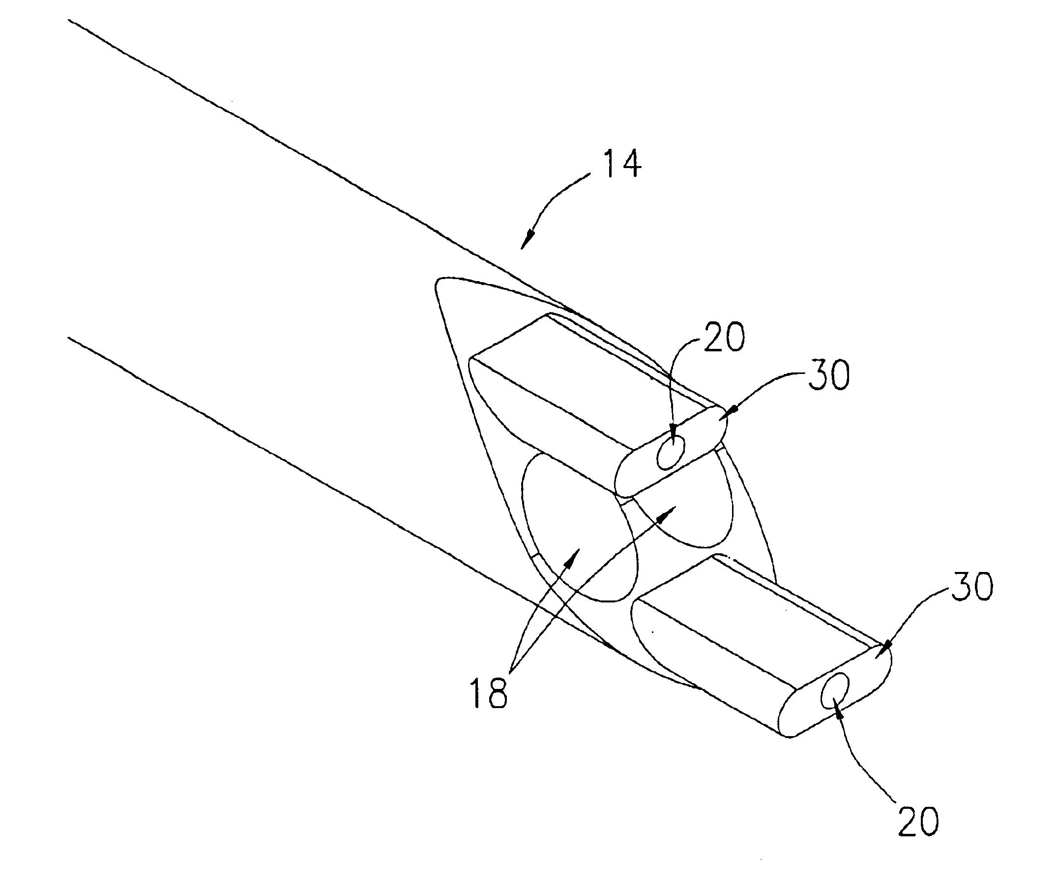
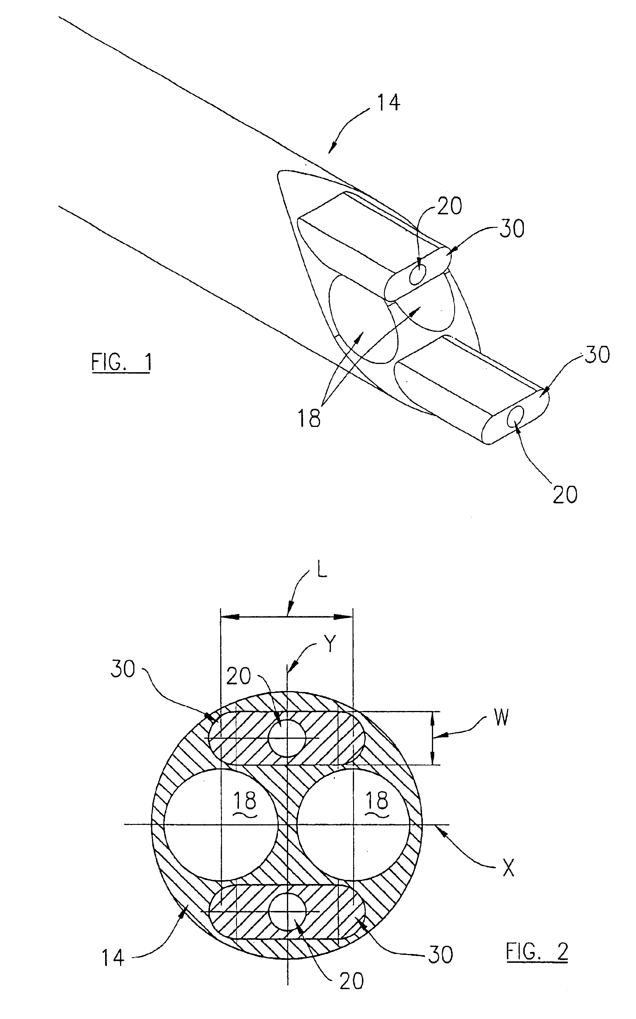
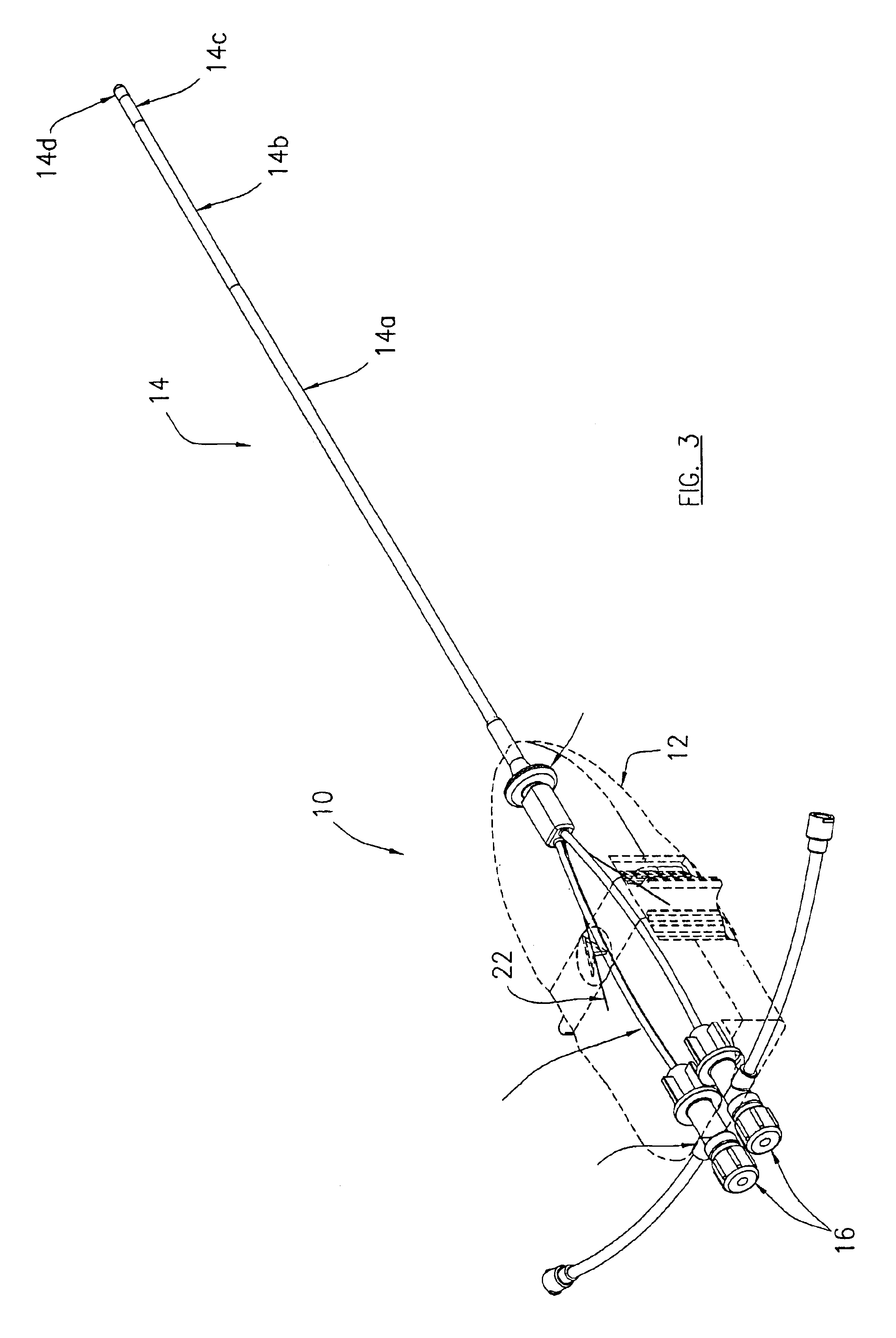
Referring now to the drawing figures, in which like reference numbers refer to like parts throughout, preferred forms of the present invention will now be described by way of example embodiments. It is to be understood that the embodiments described and depicted herein are only selected examples of the many and various forms that the present invention may take, and that these examples are not intended to be exhaustive or limiting of the claimed invention. Also, as used in the specification including the appended claims, the singular forms “a,”“an,” and “the” include the plural unless the context clearly dictates otherwise. Ranges may be expressed herein as from “about” or “approximately” one particular value and / or to “about” or “approximately” another particular value. When such a range is expressed, another embodiment includes from the one particular value and / or to the other particular value. Similarly, when values are expressed as approximations, by use of the antecedent “about,...


PUM

PropertyMeasurementUnit
lengthaaaaaaaaaa
dimensionaaaaaaaaaa
hardnessaaaaaaaaaa

Abstract

A steerable catheter having a shaft with one or more internal stiffeners coextruded within the shaft along a portion of its length. The internal stiffeners have a higher or lower hardness than the body of the catheter shaft. The overall stiffness of the shaft varies along its length for improved steerability.

Description

BACKGROUND OF THE INVENTION1. Field of the InventionThe present invention relates generally to remote access devices, and more particularly to a steerable catheter having one or more stiffeners coextruded into the catheter shaft.2. Description of Related ArtModern medical practitioners frequently gain access to internal regions of a human or animal patient's body through the use of medical catheters in a variety of medical procedures. For example, medical catheters may be used to access internal body regions with a fiberoptic scope, light bundles, surgical instruments, medications, and / or other substances and devices, for a variety of diagnosis, treatment and / or material delivery purposes. These minimally invasive catheter access techniques can significantly reduce or eliminate the need for more invasive procedures.Steerable catheters have been developed to provide improved access to remote sites such as internal body tissue. These catheters typically include a flexible catheter sha...

Claims


Application Information

Patent Timeline
Patent Type & Authority Patents(United States)
IPC IPC(8): A61M25/01A61M25/00A61M25/16
CPCA61M25/0012A61M25/0144A61M25/0147A61M25/0141A61M25/0054A61M2025/0063
Inventor BON, EDWIN
Owner MYELOTEC CO LTD
Why Eureka
Try Eureka