Method for connecting insulator coated wire
a technology of insulator coating and conductive wire, which is applied in the direction of yarn, chemistry apparatus and processes, transportation and packaging, etc., can solve the problems of large conduction resistance of the joint section between the insulator coated wire and the conductive member, difficulty in achieving both objects of keeping the conduction resistance fully low, and insufficient heat dissipation, etc., to achieve efficient heat dissipation, increase the quantity of heat, and achieve the effect of heat transmission
- Summary
- Abstract
- Description
- Claims
- Application Information
AI Technical Summary
Benefits of technology
Problems solved by technology
Method used
Image
Examples
first embodiment
[First Embodiment]
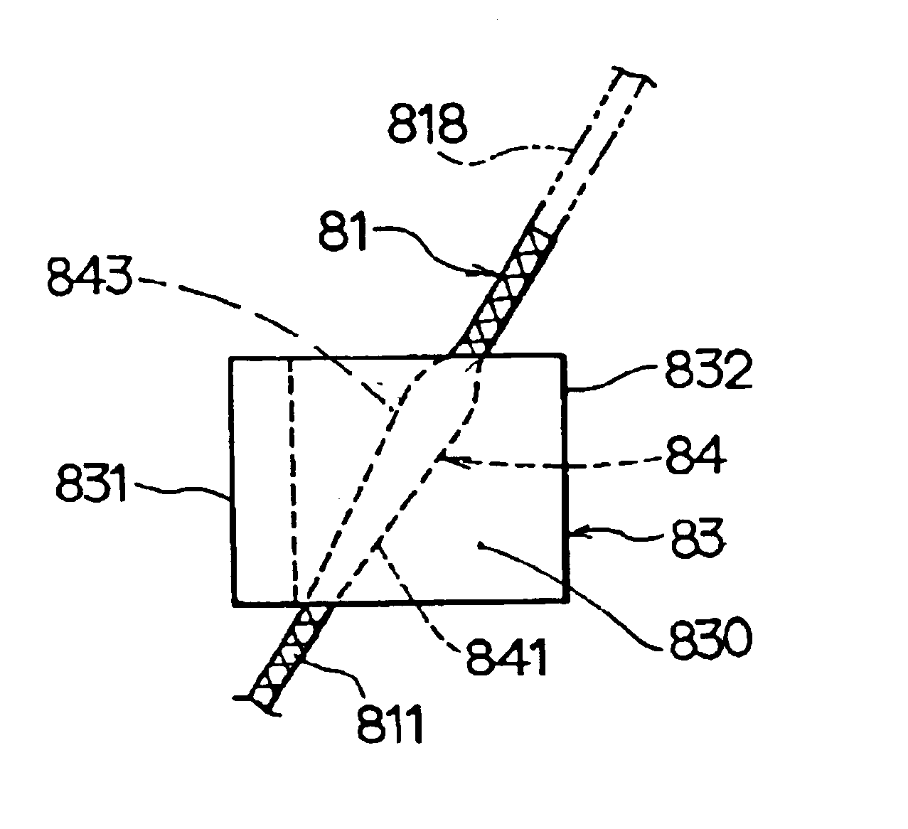
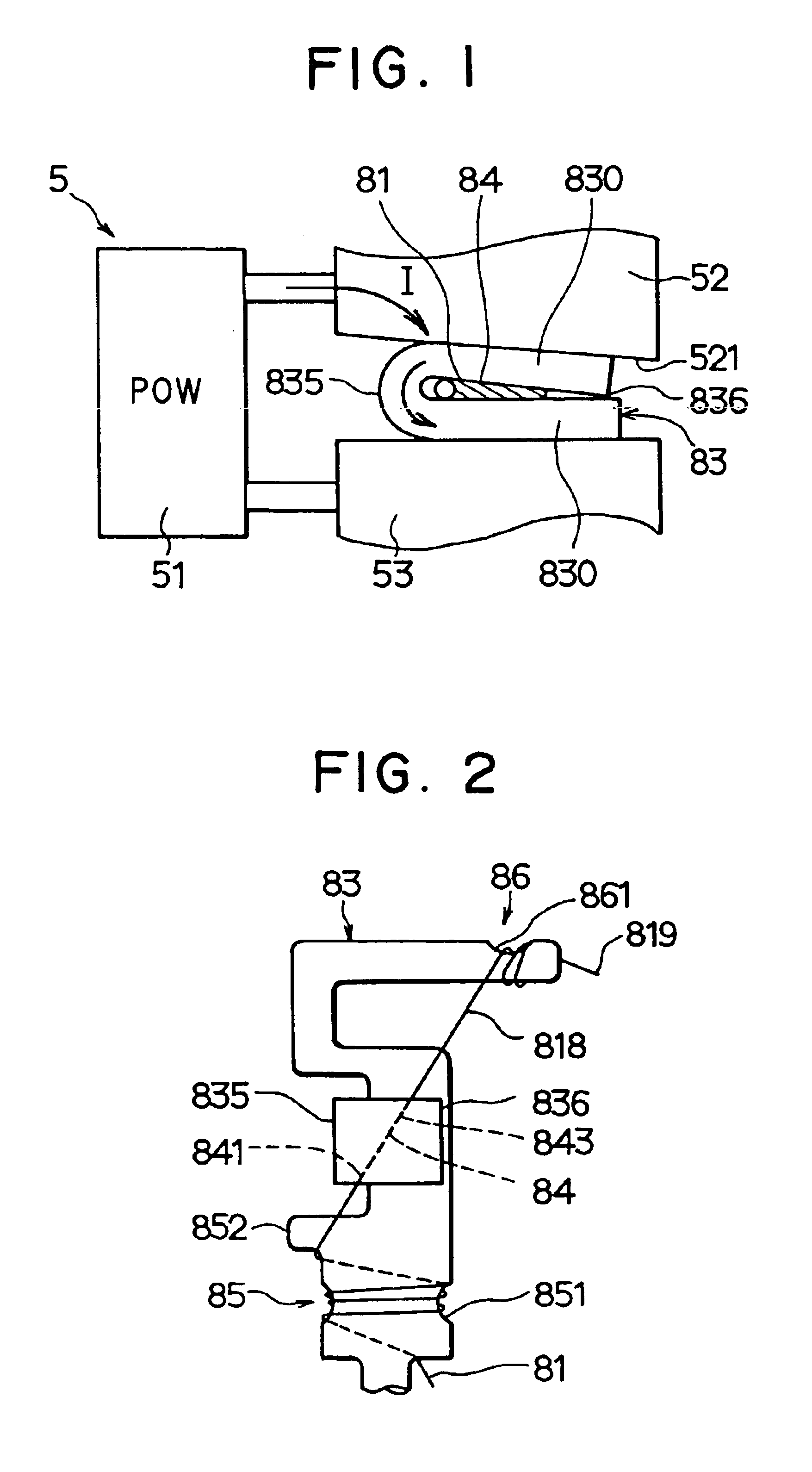
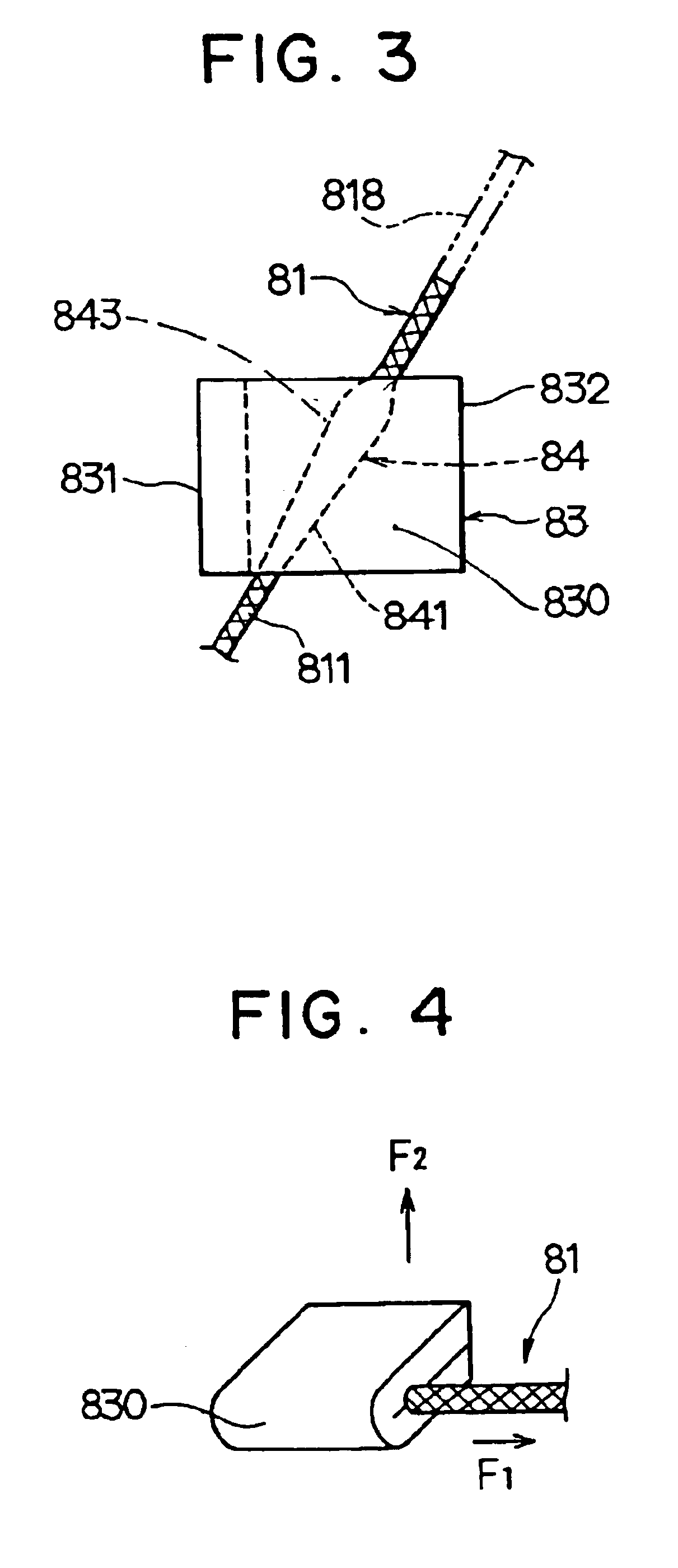
The present embodiment relates to a method for connecting an insulator coated wire 81 having an insulator coating film 811 (FIG. 3) with a conductive member 83 by means of resistance welding while pressing them as shown in FIGS. 1 through 3. The insulator coated wire 81 is pressed and connected with the conductive member 83 so that a first portion or region (e.g. the region having a cross-section profile shown in FIG. 12C) where a pressed deformation is large (the distal segment) and a second portion or region (e.g. the region having a cross-section profile shown in FIG. 12B) where the pressed deformation is small (the proximal segment) are formed at its connecting section 84. As shown in FIGS. 3 and 12, connecting section 84 has a width in cross-section that tapers from a narrow cross-section at a first point or side 841 adjacent to the second portion to a wide cross-section at a second point or side 843 distal from the second portion. At this time, the second por...
second embodiment
[Second Embodiment]
According to the present embodiment as shown in FIG. 7, conductive members 711 and 712 are made from upper and lower pieces for pinching the insulator coated wire 81. The gap between the upper piece 711 and the lower piece 712 is widened / narrowed as the location changes by changing the thickness of each of the upper piece 711 and the lower piece 712. As a result, a good electrical conductivity can be obtained between the insulator coated wire 81 and the conductive members 711 and 712 at the region 715 where the gap is narrow and the joint strength can be maintained well at the region 716 where the gap is wide.
The other elements are the same as in the first embodiment described above.
third embodiment
[Third Embodiment]
According to the present embodiment as shown in FIG. 8, the shape of the conductive members 721 and 722 is modified from the conductive members 711 and 712 of the second embodiment. As a result, good conductivity can be obtained at the region 725 where the gap is narrow and the joint strength can be maintained well at the region 726 where the gap is wide.
The other elements are the same as in the first embodiment described above.
PUM
| Property | Measurement | Unit |
|---|---|---|
| diameter | aaaaa | aaaaa |
| thickness | aaaaa | aaaaa |
| area | aaaaa | aaaaa |
Abstract
Description
Claims
Application Information
 - R&D
- Intellectual Property
- Life Sciences
- Materials
- Tech Scout
- Unparalleled Data Quality
- Higher Quality Content
- 60% Fewer Hallucinations
Browse by: Latest US Patents, China's latest patents, Technical Efficacy Thesaurus, Application Domain, Technology Topic, Popular Technical Reports.
© 2025 PatSnap. All rights reserved.Legal|Privacy policy|Modern Slavery Act Transparency Statement|Sitemap|About US| Contact US: help@patsnap.com


