Brush device

Active Publication Date: 2005-02-15
DENSO CORP +1
View PDF9 Cites 8 Cited by
  • Summary
  • Abstract
  • Description
  • Claims
  • Application Information

AI Technical Summary

Benefits of technology

Accordingly, it is an objective of the present invention to provide a brush device that shortens t

Problems solved by technology

When the terminals are retained in the vicinity of the inner portions of the brush holders, the electric wires become loose after the brushes are assembled.
Therefore, the ma

Method used


Image

  • Brush device
  • Brush device
  • Brush device

Examples


Embodiment Construction

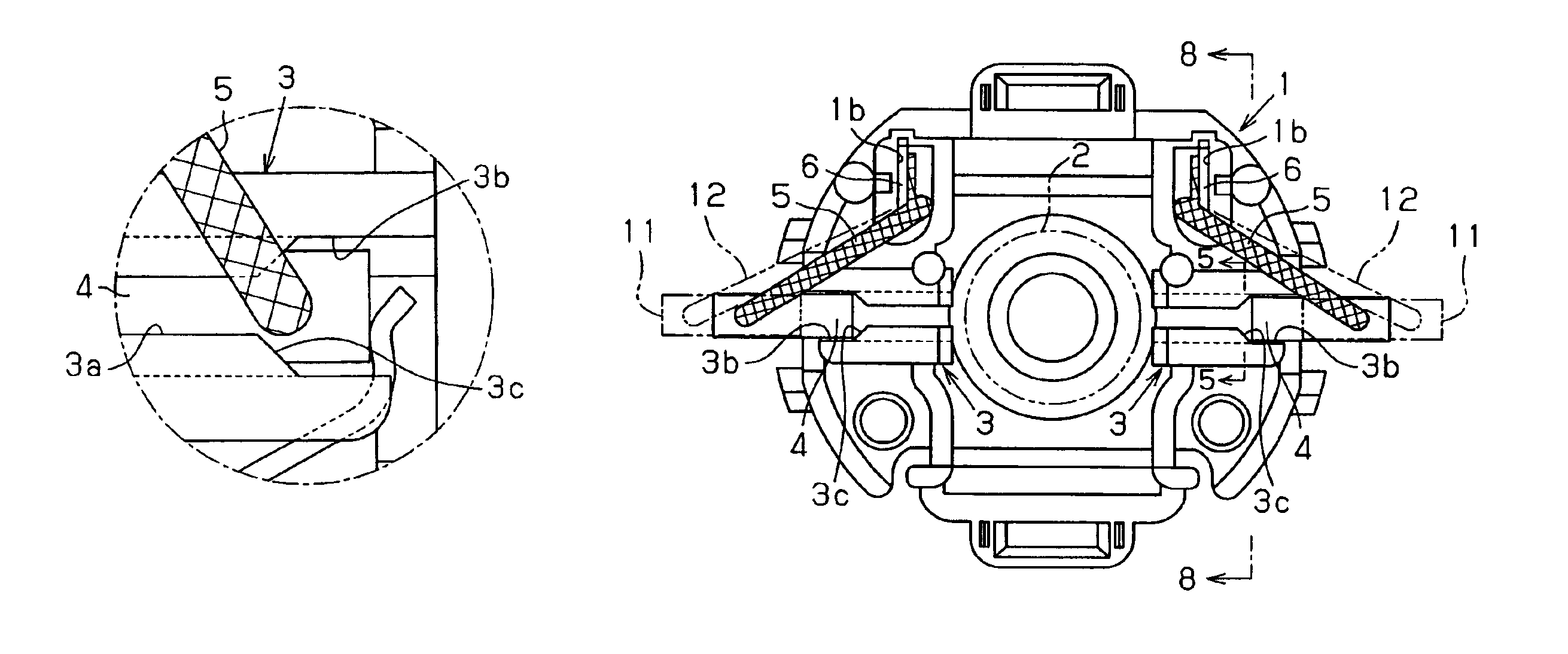
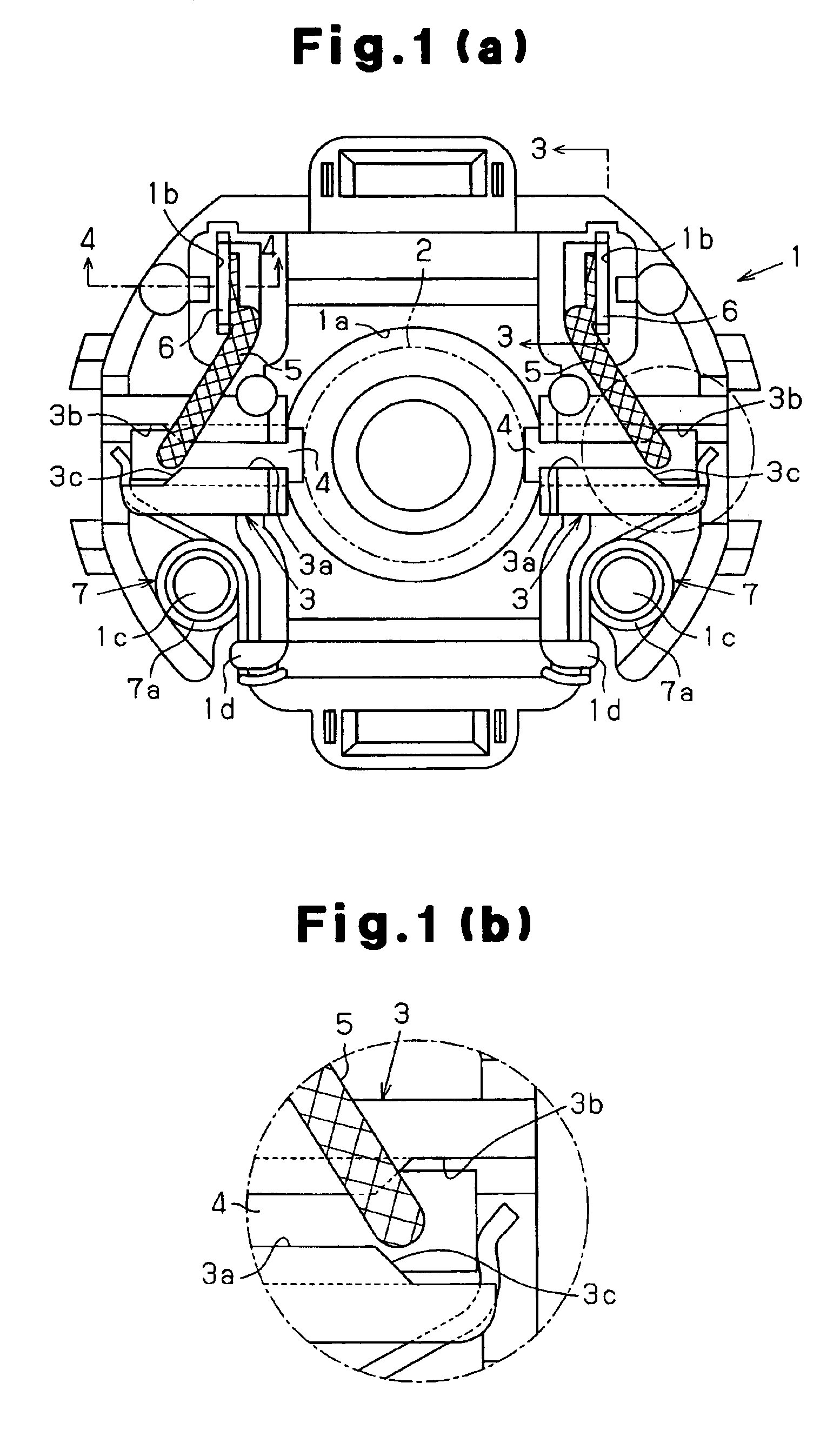
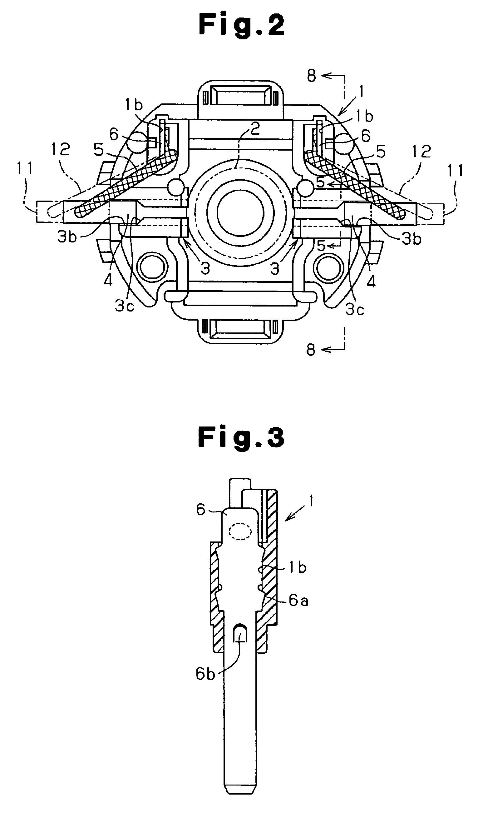
A preferred embodiment of the present invention will now be described with reference to FIGS. 1(a) to 6. FIG. 1(a) shows a base member 1, which is secured to an opening of a yoke (not shown). The base member 1 is formed with a substantially disk-like resin material.

A center bore 1a is formed at the center of the base member 1. A cylindrical commutator 2 (shown by a chain double-dashed line in FIGS. 1(a) and 2) of an armature, which is not shown, is inserted through the center bore 1a. A pair of brush holders 3 is located on the base member 1 at intervals of 180 degrees about a rotor, which is the commutator 2 in the preferred embodiment. Each brush holder 3 is substantially a rectangular tube (see FIG. 5) and has a holder axis, which extends in the radial direction of the commutator 2. An opening portion 3b is formed at the outer portion of each brush holder 3 with respect to the radial direction of the commutator 2. As shown in FIGS. 1(a) and 2, two retaining holes 1b are formed in...


PUM


Abstract

A brush device has a brush that slides against an outer circumferential surface of a cylindrical rotor. The brush device includes a base member, a terminal retained by the base member, an electric wire, which connects the brush to the terminal, and a cylindrical brush holder. The brush holder is located on the base member. The brush holder has a holder axis, which extends along the radial direction of the rotor. The brush is accommodated in and retained by the brush holder and is movable along the holder axis. The brush holder has an opening portion, which is formed at the outer portion of the brush holder with respect to the radial direction of the rotor. The opening portion permits the brush to pass along a direction perpendicular to the holder axis.

Description

BACKGROUND OF THE INVENTIONThe present invention relates to a brush device.A conventional brush device for a DC motor includes a base member, supply brushes, brush holders, and elongated terminals. The supply brushes slide against a cylindrical commutator of the motor. Each brush holder is a substantially rectangular tube and retains one of the brushes. Each terminal is retained by the base member and is connected to one of the brushes with an electric wire. The brush holders are secured to a yoke of the DC motor. Each brush holder has a ceiling that extends in the radial direction of the commutator.To assemble the brush device, each terminal is inserted into the base member from the axial direction of the commutator and is retained at a predetermined position of the base member. Then, each brush is inserted into one of the brush holders by shifting the brush from the outer portion of the brush holder to the inner portion of the brush holder in the radial direction of the commutator...

Claims


Application Information

Patent Timeline
IPC IPC(8): H02K5/14H02K5/22H01R39/00H01R39/41H01R39/36H01R39/38H02K13/00
CPCH02K5/225H02K5/148H01R39/41H01R39/36H01R39/383
Inventor TAKAHASHI, TERUMITSUYAMAMURA, MASASHIITO, KAZUTOSHIIZUMI, HIKOSHIMATSUSHIMA, KENJIIIZUKA, MAKOTO
Owner DENSO CORP
Why Eureka
Try Eureka