
Scheme to improve performance of timing recovery systems for read channels in a disk drive

a timing recovery and disk drive technology, applied in the field of data storage systems, can solve problems such as errors, inaccurate ideal levels, and almost never being obtained, and achieve the effect of improving the accuracy of detection and recovery

Inactive Publication Date: 2005-02-15
BROADCOM INT PTE LTD
View PDF7 Cites 67 Cited by
  • Summary
  • Abstract
  • Description
  • Claims
  • Application Information

AI Technical Summary

Problems solved by technology

Often times, noise or other imperfections in the PR channel cause the digital output to contain values other than the ideal values.
Also, since the readback signal is almost always corrupted by noise, the obtained ‘eye’ levels will almost never be ideal.
Since the Viterbi detector only estimates the actual data bits based on the A / D output signal, it will be noted that errors may occur when the detector does not estimate correctly.
Of course, if the Viterbi detector makes errors in detecting the bits, the wrong ideal levels may be, obtained.
When a DPLL is unable to track an incoming waveform to provide accurate estimates of the sampling clock, various errors can occur in the received data.
These errors often occur in bursts when the DPLL is not tracking the incoming waveform.
These bursts occur because when the DPLL looses track of the incoming signal, the DPLL may not be able to reacquire the frequency and phase lock.

Method used


Image

  • Scheme to improve performance of timing recovery systems for read channels in a disk drive
  • Scheme to improve performance of timing recovery systems for read channels in a disk drive
  • Scheme to improve performance of timing recovery systems for read channels in a disk drive

Examples


Embodiment Construction

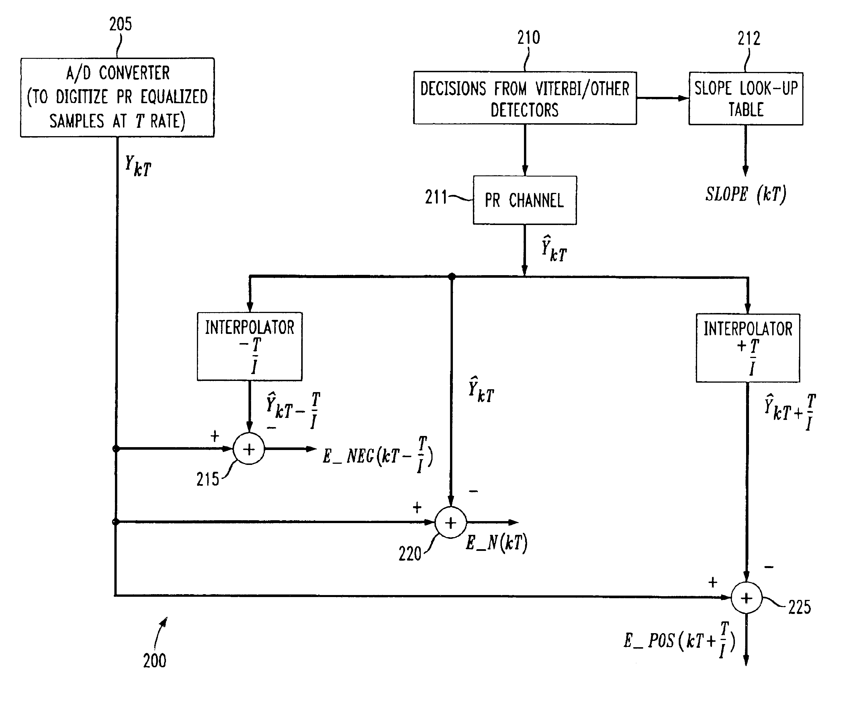
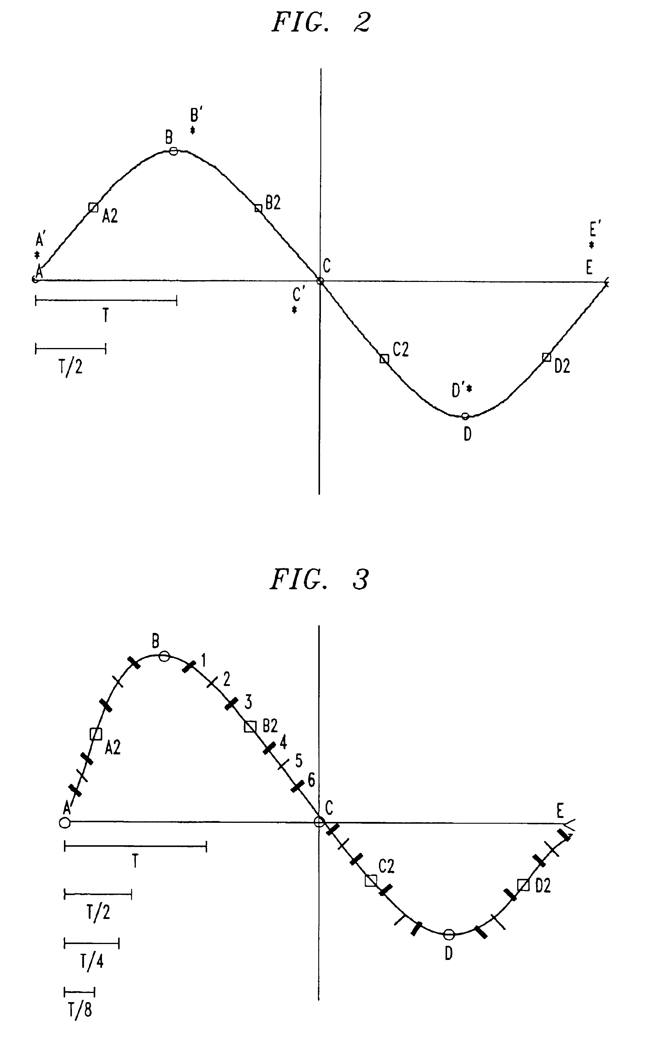
The present invention comprises a method and apparatus for detecting the direction of the drift in the sampling phase of a clock, and also the amount of drift from the ideal sampling point. This information can then be used to modify the integrators in a loop filter to provide better sampling instants going forward in tracking the data. The present invention comprises both a detection and correction scheme to avoid Loss of Lock (LOL) events.

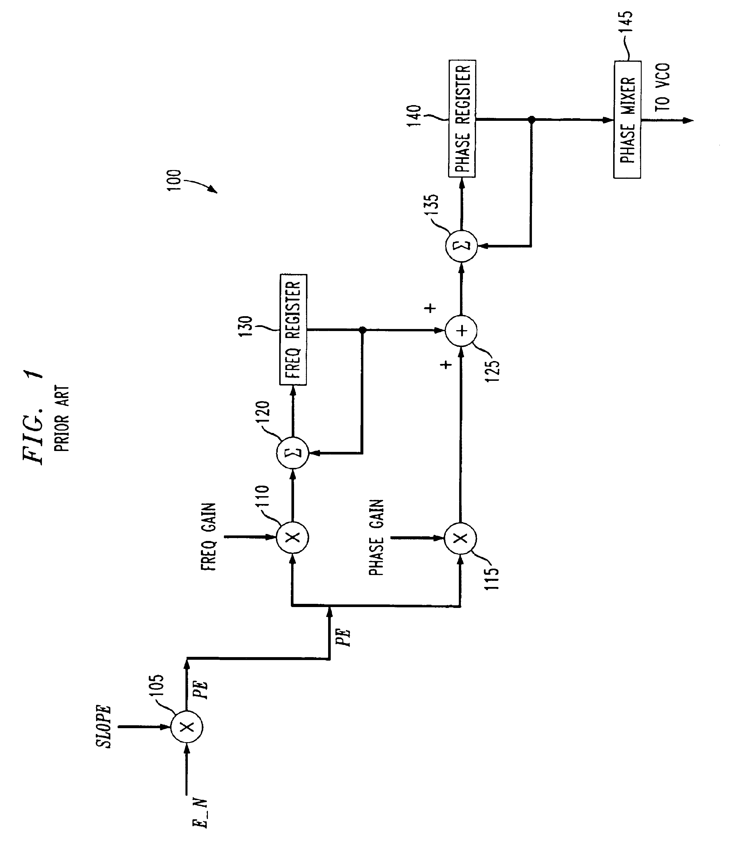
Currently, phase detectors (PDs) in digital phase locked loop (DPLL) circuits, such as DPLL 100 described above, use a single error signal (e.g., E_N(kT)) which is equal to the error between each sampled value and each ideal value at the sampling instant (symbol rate T). However, in the present invention, principles of interpolation are used to determine additional sample points which are used to generate additional error signals. Since the signal from which the error signal or signals is determined is often band-limited, it is possible to determ...


PUM


Abstract

A digital phase lock loop circuit including an error generation circuit for generating at least three error signals and a phase error adjustment circuit for generating at least one phase error adjustment signal from the at least three error signals. By using at least three error signals, as opposed to just one, the drift in the sampling phase of the recovered clock is easily detected and corrected to reduce burst errors and to improve loss of lock (LOL) performance.

Description

FIELD OF THE INVENTIONThis present invention relates data storage systems, and in particular, read channel devices for reading out information stored in data storage systems.BACKGROUND OF THE INVENTIONRead channel devices serve as interfaces between a hard disk on which digital information is stored and external devices (e.g., Central Processing Unit (CPU)) which receive and process the digital information in various applications. Read channel devices take the analog information stored as magnetic pulses on the hard disk drive and convert that information into digital values (i.e., “1”s and “0”s) that are readable by digital devices, such as a CPU.Timing recovery is an important aspect of many read channel devices. Timing recovery systems serve to recover a clock signal at the symbol rate that is both phase-locked and frequency-locked to the incoming data (i.e., from the hard disk). A typical read channel device utilizes a digital phase lock loop (DPLL) to perform timing recovery op...

Claims


Application Information

Patent Timeline
IPC IPC(8): G11B20/18H03L7/091H03L7/08G11B5/012G11B5/09
CPCH03L7/091G11B20/18G11B20/1403G11B5/012G11B5/09
Inventor ANNAMPEDU, VISWANATH
Owner BROADCOM INT PTE LTD
Learn More