Harmonic filtering circuit with special transformer

a filter circuit and transformer technology, applied in the field of filter circuits, can solve the problems of wasting harmonic energy, wasting harmonic energy, and turning into heat, and achieve the effect of simple and inexpensiv

Inactive Publication Date: 2005-02-15
LU WEIMIN
View PDF22 Cites 41 Cited by
  • Summary
  • Abstract
  • Description
  • Claims
  • Application Information

AI Technical Summary

Benefits of technology

It is an object of the present invention to remove substantially all of the harmonics of the fundamental frequency from the distorted waveform of an alternating current power line by means of a relatively simple and inexpensive filter incorporating a special autotransformer that generates an inductive reactance within itself and a tuning capacitor that tunes that inductive reactance to the fundamental frequency so that only alternating current at the fundamental frequency can pass through to locations farther along the power line.
Another object is to simplify the manufacture of harmonic-removing filters for alternating current power lines and to reduce the size and cost of such filters in comparison with other filtering means capable of achieving more or less the same degree of filtering.
Yet another object is to form a built-in inductor in the secondary and to tune this inductor with a single capacitor to substantially reduce all harmonics of the fundamental frequency in a power line carrying a distorted alternating current.
It is also an object of this invention to reduce the rise of temperature in the components, including the transformer core, the capacitor, and the secondary winding of a filter capable of reducing substantially the amplitude of even the lowest harmonics of the fundamental frequency of an alternating current power line.
The magnitude of the output voltage can be brought back up to that of the input voltage by providing a third winding as part of the second coil and connecting this third winding in series between the first output terminal and the junction between the first coil and the first winding of the second coil. The third winding shares in the inductive effect that applies to the first and second windings of the second coil, and thus the voltage across the third winding is at least substantially in phase with the voltage across the first and second windings. This allows the magnitude of the voltage across the third winding to simply be added to the magnitude of the voltage across the first winding so that the substantially harmonic-free output voltage of the filter is brought back up to the nominal voltage of the power line, or even higher.

Problems solved by technology

While the transformer-based circuits disclosed in my prior applications remove harmonics from the waveform of alternating current transmitted through them, those circuits are too expensive if it is not necessary to hold the magnitude of the output voltage close to a certain value, but instead to allow it to vary with the magnitude of the input voltage, which may vary within a range of about ±15%.
It is also possible to use individual harmonic traps tuned, for example, to the 3rd, 5th, and 7th harmonics to remove them, but providing a separate trap for each harmonic is a very expensive way of achieving a harmonic-free output, and the harmonic energy removed by such traps is completely wasted and turned into heat.

Method used


Image

  • Harmonic filtering circuit with special transformer
  • Harmonic filtering circuit with special transformer
  • Harmonic filtering circuit with special transformer

Examples


Embodiment Construction

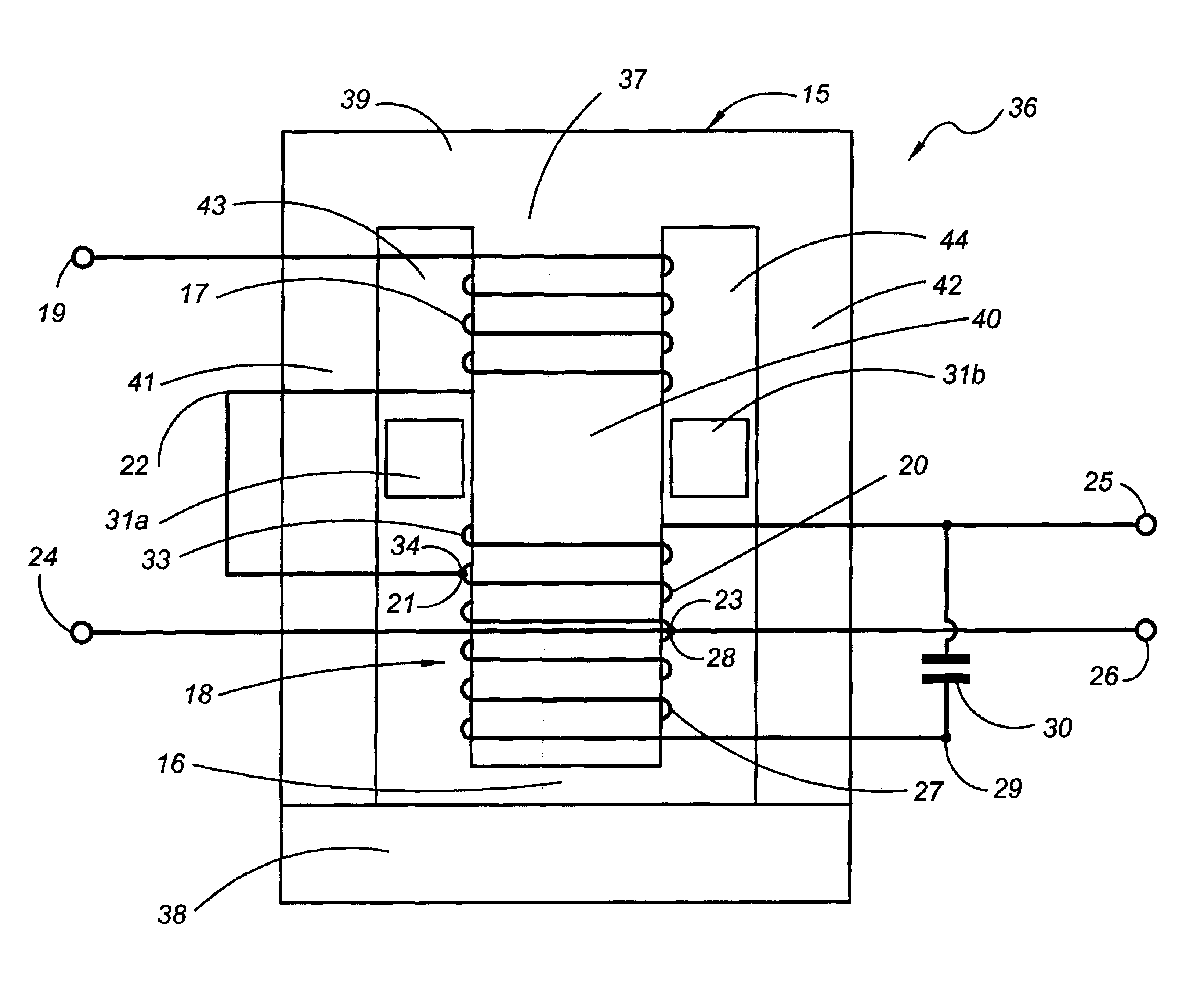
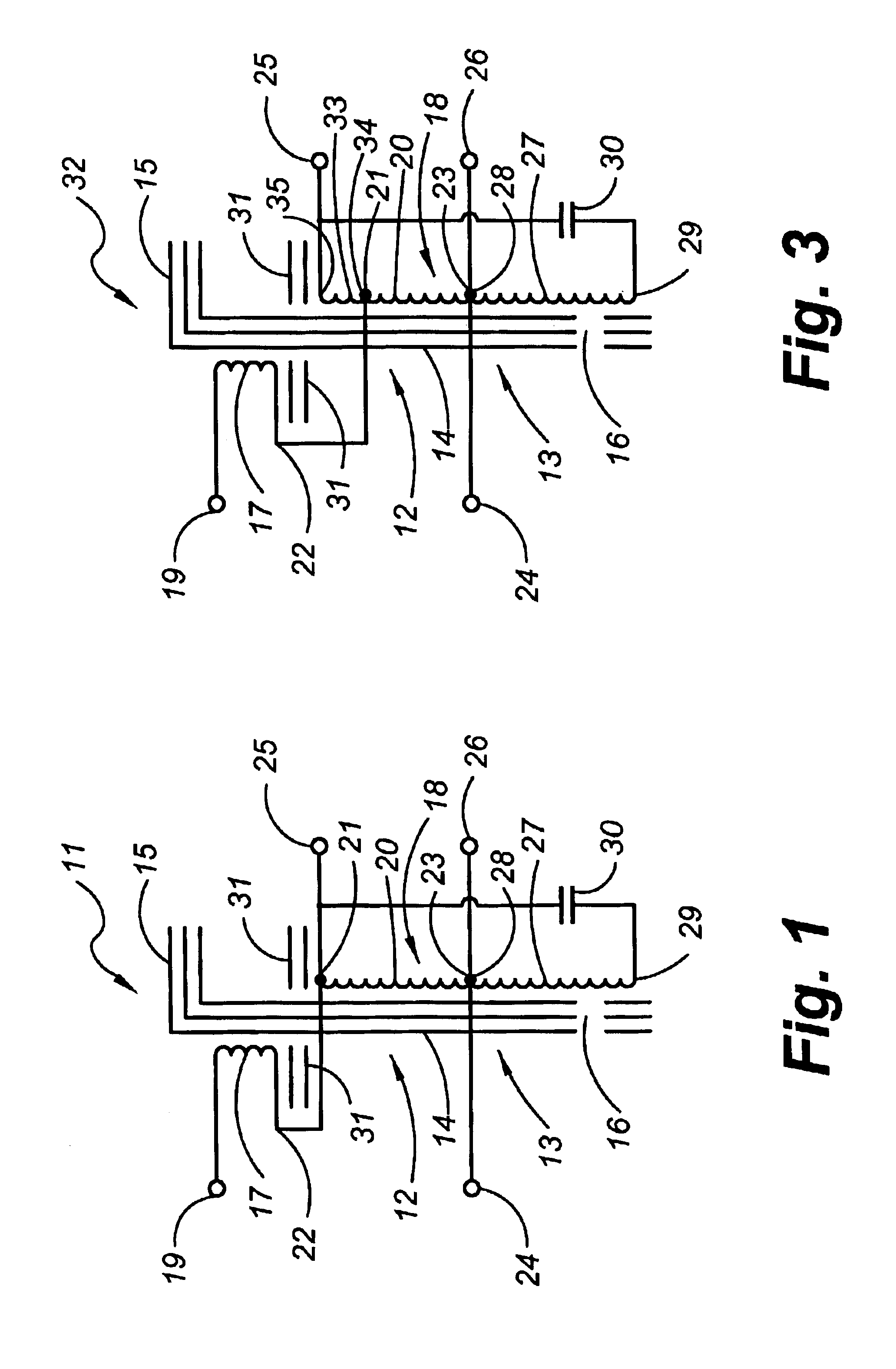
FIG. 1 shows a filter circuit 11 comprising a special autotransformer 12 with a ferromagnetic core 13 that has a plurality of legs and bars that are parts of a low-reluctance flux path and include winding leg means 14 and flux return means 15. The core also has a region of substantially increased reluctance, such as an air gap 16. First and second coils 17 and 18 are in spaced-apart locations of the winding leg means 14, with one terminal 19 of the first coil serving as a first input terminal of the filter circuit. The second coil 18 includes a first winding 20 that has a first terminal 21 connected to a second terminal 22 of the first coil 17 to form a first series circuit from the terminal 19 to a second terminal 23 of the winding 20. The terminal 23 is connected to a second input terminal 24, so that the first coil 17 and the first winding 20 of the second coil 18 form the input circuit of the filter 11.

The connection between the terminals 21 and 22 is connected to a first output...


PUM

PropertyMeasurementUnit
currentaaaaaaaaaa
currentaaaaaaaaaa
currentaaaaaaaaaa

Abstract

A filter uses a special autotransformer that has a ferromagnetic core with a plurality of legs and flux return bars. A first coil is located on one leg, and a second coil is located on the same leg, but spaced from the first coil. The first coil and at least part of the second coil are connected in series to receive distorted alternating current and at least that part of the second coil is connected to an output terminal. Between the coils and extending at least part of the way from the first leg to an adjacent leg is a magnetic shunt assembly to divert part of the flux generated in the first coil by the alternating current so that that part does not link with the second coil. An air gap is located to link with the second coil to create an inductor in that coil by flux in the second coil, and a capacitor is connected across the second coil to tune it to the fundamental frequency of the alternating current and substantially reduce harmonics in that current.

Description

BACKGROUND OF THE INVENTION1. Field of the InventionThis invention relates to filtering circuits to reduce harmonics in the alternating current from a power source, such as a public utility. The alternating current is expected to have a sinusoidal waveform at a certain frequency, which is the waveform required for many types of electrical apparatus. When the waveform is distorted at some location along the power line, the distortion takes the form of harmonics of the fundamental frequency, and those harmonics cannot be used in the way that the fundamental alternating current can; they are power losses to the utility and can be detrimental to equipment being used by other customers connected to the alternating current source by the same power line. As a result, utilities increase their charge to customers whose equipment produces such harmonics, and in order to reduce such increased charges, the customers who incur those charges would like to be able to filter out the harmonics.2. Th...

Claims


Application Information

Patent Timeline
Patent Type & Authority Patents(United States)
IPC IPC(8): H01F27/34H01F27/38H03H1/00
CPCH01F27/385H02J3/01H03H1/0007Y02E40/40H03H2001/0057
Inventor LU, WEIMIN
Owner LU WEIMIN
Why Eureka
Try Eureka