Adjustable antenna

a technology of adjustable antennas and antenna supports, applied in the direction of collapsable antennas, telescopic elements, antenna supports/mountings, etc., can solve the problems of increased manufacturing costs of antennas, increased installation costs, and insufficient antenna characteristics, etc., and achieve the effect of adjusting the manufacturing cost of antennas

Inactive Publication Date: 2005-02-15
PULSE FINLAND
View PDF9 Cites 40 Cited by
  • Summary
  • Abstract
  • Description
  • Claims
  • Application Information

AI Technical Summary

Benefits of technology

An advantage of the invention is that an antenna according to it can be adjusted electrically without adding any component in the antenna itself. This brings the additional advantage that the adjustment is reliable since there cann...

Problems solved by technology

In the latter case there is, however, the risk that the antenna characteristics are not satisfactory e.g. in part of the wide operating band.
A drawback of this met...

Method used


Image

  • Adjustable antenna
  • Adjustable antenna
  • Adjustable antenna

Examples


Embodiment Construction

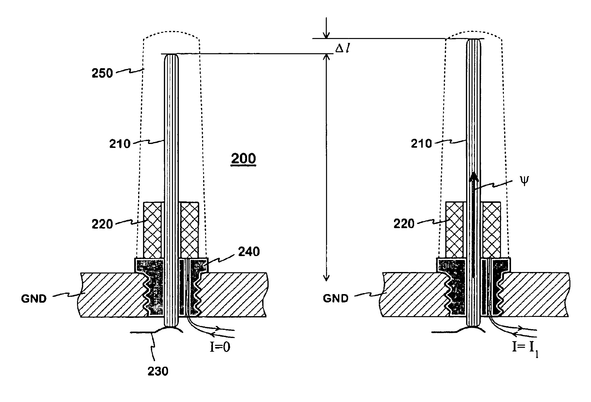
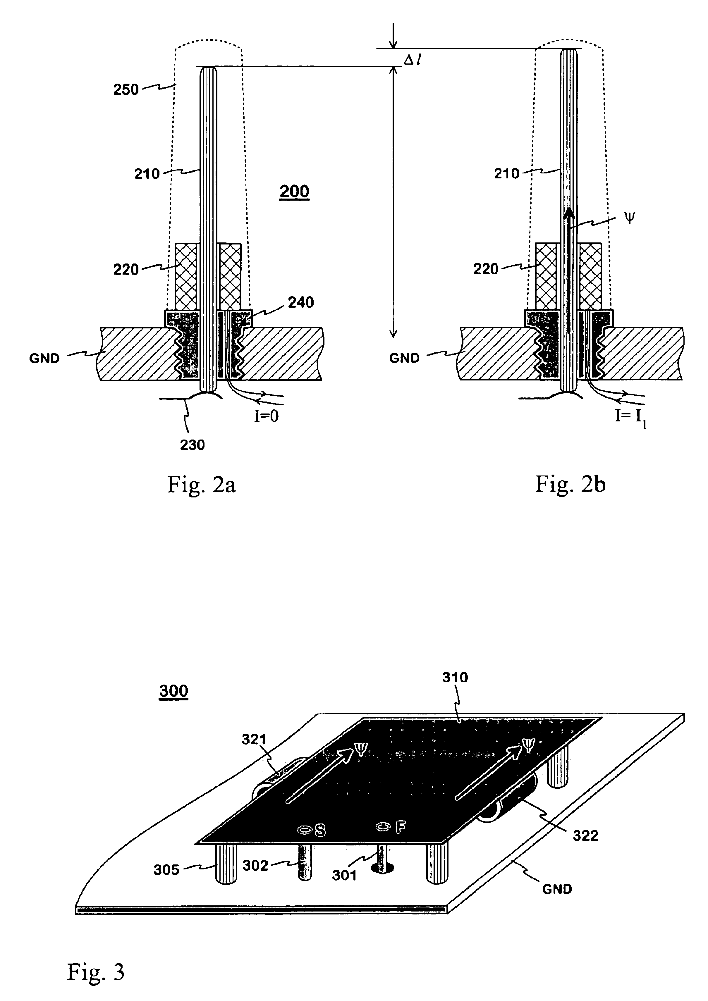
In FIGS. 2a and b, the invention is applied to a monopole antenna. The antenna structure 200, shown in longitudinal section, comprises a radiating monopole element 210 the length of which corresponds to a quarter of the wavelength at the operating frequency, and a winding 220 which constitutes an electromagnet. Functionally, the antenna structure comprises the frame GND of the radio apparatus in question, serving as a ground plane, to which the radiating element 210 is fastened through an insulating element 240. The radiating element is connected at its lower end to the antenna port of the radio apparatus through a feed conductor 230. The structure is protected by a hood 250, drawn in broken line.

In the example depicted by FIGS. 2a,b, the cylindrical winding 220 is round the lower part of the monopole element 210. In FIG. 2a, the current I through the winding 220 is zero and, therefore, there is no magnetic field generated by the winding. The monopole element has a certain electrica...


PUM


Abstract

Antenna structure (200) which finds particular utility in mobile stations and the electrical characteristics of which can be electrically modified. The radiating element (210) of the antenna or a part thereof is manufactured from a strongly magnetostrictive material. The antenna is equipped with at least one electromagnet (220) by means of which a magnetic field (ψ) can be generated into the magnetostrictive material. This causes the radiating element to grow (Δl) in a certain direction, whereby the resonance frequency of the antenna will decrease. The antenna can be electrically adjusted without adding any component in the antenna itself, thereby making the adjustment reliable.

Description

The invention relates to an antenna structure which finds particular utility in mobile stations and the electrical characteristics of which can be electrically modified.BACKGROUND OF THE INVENTIONModifiability of antenna structure is a preferable characteristic in communications devices designed to be used in more than one radio system. Such systems include e.g. the AMPS (Advanced Mobile Phone System), GSM900 (Global System for Mobile Telecommunications), DCS (Digital Cellular System), GSM1800, GSM1900, WCDMA (Wideband Code Division Multiple Access) and UMTS (Universal Mobile Telecommunication System). An antenna may be construed so as to have two separate operating bands which cover the frequency ranges used by the different systems, or so as to have a single, relatively wide, operating band which covers the frequency ranges of at least two systems. In the latter case there is, however, the risk that the antenna characteristics are not satisfactory e.g. in part of the wide operatin...

Claims


Application Information

Patent Timeline
IPC IPC(8): H01Q1/10H01Q9/04H01Q1/24H01Q9/30H01Q1/08
CPCH01Q1/10H01Q9/30H01Q1/243
Inventor BORDI, MIKA
Owner PULSE FINLAND
Why Eureka
Try Eureka