Optical disk player

a technology of optical disk and optical disk, which is applied in the direction of digital signal error detection/correction, instruments, recording signal processing, etc., can solve the problems of inability to securely write data, the rotational speed of the optical disk for writing data in an inner part is too fast to secure write data, and the inability to read correct efm data patterns, etc., to achieve the effect of preventing the production of useless disks and slowing down the writing speed

Inactive Publication Date: 2005-02-15
SHINANO KENSHI
View PDF12 Cites 5 Cited by
  • Summary
  • Abstract
  • Description
  • Claims
  • Application Information

AI Technical Summary

Benefits of technology

In the zone CLV type optical disk player, after the interruption of writing data, writing data is restarted at faster writing velocity, so the zone CLV control means tries to synchronize the rotation of the optical disk with the faster writing veloc...

Problems solved by technology

In the conventional optical disk player, if writing data is interrupted by buffer under-run, the optical disk cannot be used any longer.
In the CLV type optical disk player, if the linear velocity is merely accelerated, the rotational speed of the optical disk for writing data in an inner part is too fast to securely write data.
However, if quality of written data is low due to high writing velocity, correct EFM data patterns ...

Method used


Image

  • Optical disk player
  • Optical disk player
  • Optical disk player

Examples


first embodiment

(First Embodiment)

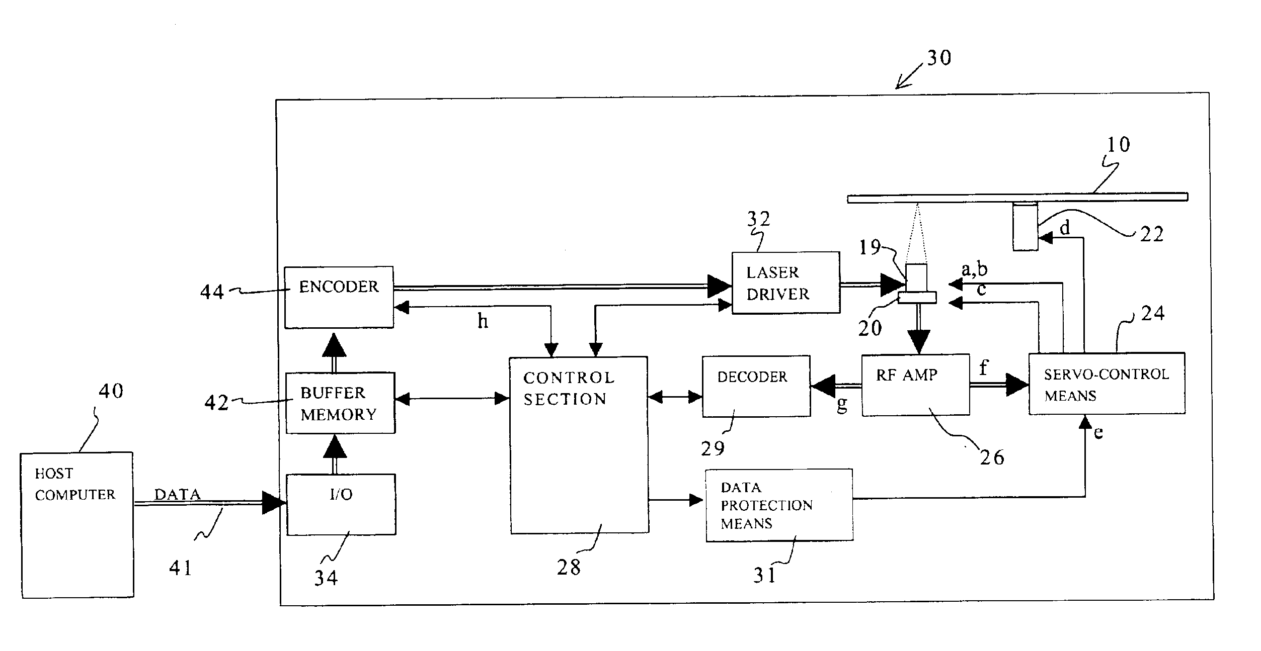
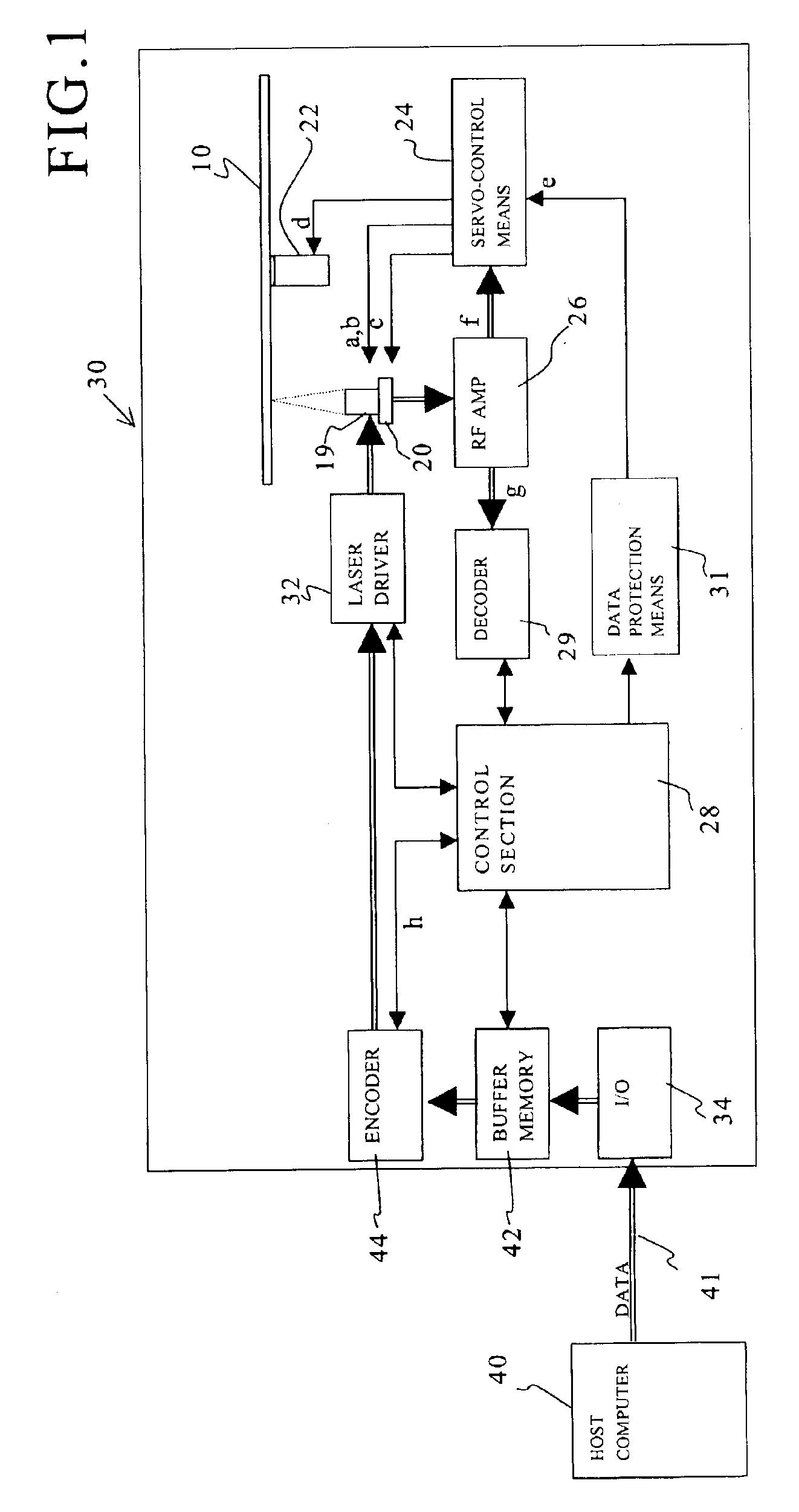
Firstly, a structure of an optical disk player of a first embodiment will be explained with reference to a block diagram shown in FIG. 1.

The optical disk player 30 has an optical pick-up 19, which includes a laser diode (not shown) irradiating laser beams toward an optical disk 10 and a photo detector (not shown) receiving laser beams reflected from the optical disk 10.

The optical pick-up 19 is moved in a tracking direction of the optical disk 10 by a moving mechanism 20. The moving mechanism 20 includes a thread shaft (not shown) for movably supporting the optical pick-up 19, a motor (not shown) for rotating the thread shaft, etc.

The optical disk 10 is mounted on a turn table, which is fixed to a rotary shaft of a spindle motor 22. Therefore, the spindle motor 22 rotates the optical disk 10.

Servo-controlling means 24 controls the spindle motor 22 for rotating the optical disk 10, tracking and focusing an object lens (not shown) assembled in the optical pick-up 19,...

second embodiment

(Second Embodiment)

A structure of an optical disk player of a second embodiment will be explained with reference to FIG. 4. Note that, structural elements described in the first embodiment are assigned the same symbols, and explanation will be omitted.

In the present embodiment, the control section 28 include a zone CLV control means 48. The zone CLV control means 48 controls the servo-controlling means 24 to accelerate the writing velocity, by stages, with outwardly writing data, zone by zone, from an inner zone of the optical disk 10.

The zone CLV control will be explained with reference to FIG. 5.

As shown in FIG. 5, a data writing area of the optical disk 10 is divided into a plurality of zones 50, 52 and 54 in the radial direction. The writing velocity is accelerated, by stages, toward the outermost zone 54. In each zone, data are written at a constant linear velocity.

In the present embodiment, the writing linear velocities are a 16X velocity (zone 50), a 20× velocity (zone 52) an...

third embodiment

(Third Embodiment)

A structure of an optical disk player of a third embodiment will be explained with reference to FIG. 7. The third embodiment a combination of the first and the second embodiments. Note that, structural elements described in the former embodiments are assigned the same symbols, and explanation will be omitted.

In the present embodiment, the zone CLV control means 48 controls the servo-controlling means 24 to accelerate the writing velocity, by stages, with outwardly writing data, zone by zone, from the inner zone of the optical disk 10. Further, when the buffer under-run occurs, the data protection means 31 interrupts writing data so as not to produce useless disks.

In the optical disk player of the third embodiment, the data protection means 31 acts as the flow chart of FIG. 3 so as to protect data; the zone CLV control means 48 acts as the flow chart of FIG. 6 when the writing velocity is changed.

Namely, if writing data is interrupted due to protecting data or chang...


PUM


Abstract

The optical disk player is capable of correctly restarting to write data. Data protection means returns an optical pick-up from an interruption address to a synchronization starting address. The data protection means reads data from the synchronization starting address to the interruption address at a reading velocity equal to a former writing velocity. The data protection means restarts writing data from the interruption address if a phase of data read is synchronized with a phase of data to be written. The data protection means returns the optical pick-up to the synchronization starting address and reads data from there to the interruption address at a reading velocity slower than the former writing velocity so as to synchronize the phases if the synchronization is failed.

Description

BACKGROUND OF THE INVENTIONThe present invention relates to an optical disk player, more precisely relates to an optical disk player, which is capable of restarting to write data from an interruption address even if writing data is once interrupted.In an optical disk player, data are written on an optical disk. These days, a velocity of writing data on the optical disk is made higher and higher, so that a velocity of transferring data to be written from a host computer to the optical disk player is often slower than the velocity of writing data. This phenomenon is called “buffer under-run”.In the conventional optical disk player, if writing data is interrupted by buffer under-run, the optical disk cannot be used any longer.To solve the problem caused by buffer under-run, recently many optical disk players have data protection means so as to prevent producing useless disks.The data protection means will be explained. When the buffer under-run occurs, the data protection means interru...

Claims


Application Information

Patent Timeline
IPC IPC(8): G11B20/10G11B7/0045G11B7/007G11B7/085G11B19/28G11B20/14G11B20/18
CPCG11B20/10527G11B7/08505G11B7/0079G11B2020/10814
Inventor HARADA, TAKASHI
Owner SHINANO KENSHI
Why Eureka
Try Eureka