Microphone holder having connector unit molded together with conductive strips

a technology of connector unit and connector strip, which is applied in the direction of microphone structure association, piezoelectric/electrostrictive transducer, transducer type, etc., can solve the problems of low production efficiency of prior art microphone holder, large amount of manual labor, and low production efficiency of microphone holder. achieve the effect of speeding up the assembling work

Inactive Publication Date: 2005-02-15
YAMAHA METANIX CORP
View PDF13 Cites 29 Cited by
  • Summary
  • Abstract
  • Description
  • Claims
  • Application Information

AI Technical Summary

Benefits of technology

It is therefore an important object of the present invention to provide a microphone holder, which makes a manufacturer speed up the assembling work.

Problems solved by technology

The manual labor consumes a large amount of time so that the manufacturer suffers from low producibility of the prior art microphone holder.
This is the first problem inherent in the prior art microphone holder.
Another problem is poor design flexibility on user's side.
If the user wants to form the sound holes in such a manner that the centerlines are parallel to the virtual plane, the user can not employ the prior art microphone holder in his product.

Method used


Image

  • Microphone holder having connector unit molded together with conductive strips
  • Microphone holder having connector unit molded together with conductive strips
  • Microphone holder having connector unit molded together with conductive strips

Examples


first embodiment

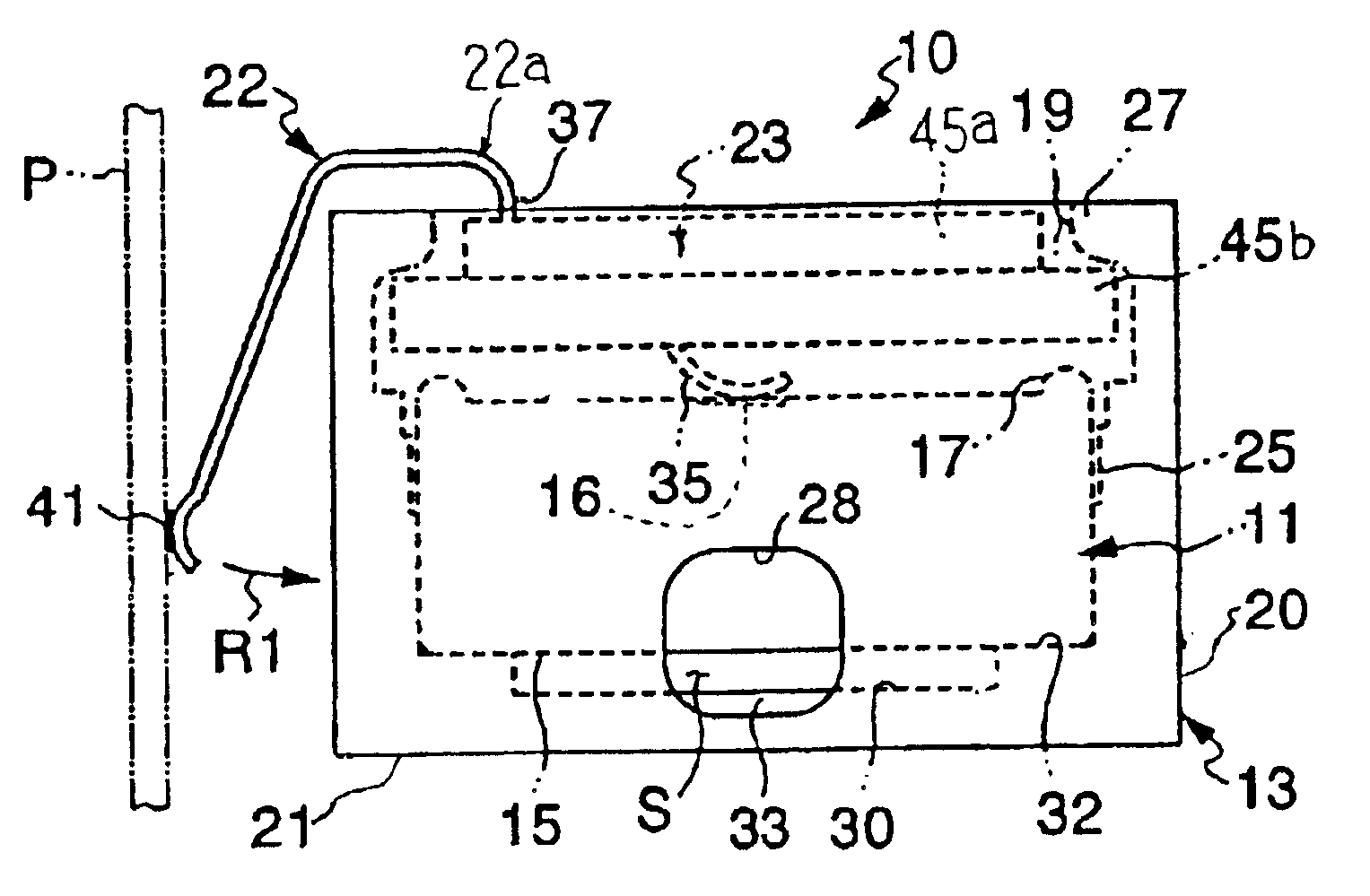
FIGS. 3, 4 and 5 show a microphone holder 10 remodeled on the basis of the microphone holder 5. The microphone holder 10 largely comprises a casing 13 and a connector unit 22. A recess 12 is formed in the casing 13, and a microphone 11 is received in the recess 12, and is closed with the connector unit 22. The connector unit 22 offers current paths to electric power and an electric signal flowing between a circuit board P and the microphone 11. A sound hole 28 is further formed in the casing 13, and is open at one end thereof to the atmosphere on a side surface of the casing 13 and at the other end thereof to the recess 12. The microphone 11 has a sound sensitive surface 15, and sound wave is propagated through the sound hole 28 to the sound sensitive surface 15. The sound hole 28 is aligned with a perforated portion PF of a casing C of a communication device.

The casing 13 is made of synthetic resin in elastomer series, by way of example, and has a rectangular parallelepiped configu...

second embodiment

FIG. 8 shows another microphone holder 10A remodeled on the basis of the basic structure. The microphone holder 10A largely comprises a casing 13 and a connector unit 22. A recess 12 is formed in the casing 13, and a microphone 11 is housed in the casing. The recess 12 is closed with the connector unit 22 as similar to the microphone holder 10.

The microphone 11 and the connector unit 22 are similar to those of the microphone holder 10. Parts of the microphone / connector unit 11 / 22 are labeled with the references designating corresponding parts of the microphone holder 10 without any detailed description for the sake of simplicity.

The casing 13A is similar to the casing 13 except for a sound hole 48. The sound hole 48 is formed in the bottom wall 21, and is open at one end thereof to the lower zone S and at the other end thereof to the atmosphere. While a user is taking through a communication device, the voice or sound wave enters the sound hole 48, and reaches the sound sensitive su...

third embodiment

FIG. 9 shows yet another microphone holder 10B remodeled on the basis of the basic structure. The microphone holder 10B largely comprises a casing 13B and a connector unit 22. A recess 12 is formed in the casing 13B, and a microphone 11 is housed in the casing 13B. The recess 12 is closed with the connector unit 22 as similar to the microphone holders 10 and 10A.

The microphone 11 and the connector unit 22 are similar to those of the microphone holders 10 and 10B. For this reason, parts of the microphone / connector unit 11 / 22 are labeled with the references designating corresponding parts of the microphone holder 10 without any detailed description for the sake of simplicity.

The casing 13B is similar to the casing 13 except for sound holes 50 / 51 and closures 52a / 52b. The sound hole 50 is formed in the side wall 20, and extends between the side surface and the lower zone S. On the other hand, the sound hole 51 is formed in the bottom wall 21, and is open at the other end thereof to the...


PUM


Abstract

A microphone holder includes a casing made of soft synthetic resin and formed with a recess and a sound hole open to the recess and a connector unit having conductive elastic strips partially embedded in a solid insulating lid made of hard synthetic resin; a microphone is snugly received in the recess, and the recess is closed with the solid insulating lid in such a manner that the conductive elastic strips are held in contact at inner contact portions to electrodes of the microphone and at the outer contact portions to a circuit board; the conductive elastic strips are embedded in the solid insulating lid during a molding for the solid insulating lid so that the assembling work is speeded up.

Description

FIELD OF THE INVENTIONThis invention relates to a microphone holder and, more particularly, to a microphone holder forming a part of a communication device such as, for example, a mobile telephone or a transceiver.DESCRIPTION OF THE RELATED ARTPortable communication devices such as mobile telephones and transceivers are convenient to active people, and offer private communication to the users anywhere they are. The portable communication devices require microphones. While the user is taking into the microphone, the microphone converts the voice to an electric signal, and the electric signal is transmitted from the communication device through an exchange to the communication device of the other person. The electric signal is reconverted to voice through a suitable speaker. A microphone is also incorporated in the communication device of the other person, and the voice is also converted to an electric signal through the microphone during his or her talk. Thus, the microphone is an in...

Claims


Application Information

Patent Timeline
Patent Type & Authority Patents(United States)
IPC IPC(8): H04R21/00H04R21/02H04R1/00H04R1/02
CPCH04R1/04H04R1/06H04R1/02
Inventor SUDO, YOSHINORIFUJIWARA, NORITAKA
Owner YAMAHA METANIX CORP
Why Eureka
Try Eureka