
Downlink power control method for wireless packet data network

a power control and wireless packet technology, applied in power management, wireless communication, transmission, etc., can solve the problems of increasing the carrying capacity of data traffic of a cell, not being corrected, and airlink errors being detected

Inactive Publication Date: 2005-02-15
LUCENT TECH INC
View PDF6 Cites 75 Cited by
  • Summary
  • Abstract
  • Description
  • Claims
  • Application Information

AI Technical Summary

Benefits of technology

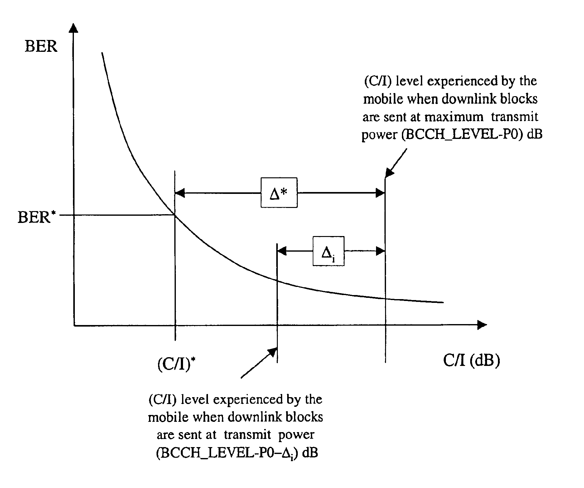
In the present invention, in which a system has a base station transmitter for transmitting data blocks to one or more mobile stations over a radio link, a method is provided for determining a transmit power level at which to transmit a current block. A quality measurement is received from a mobile station indicating an average radio link quality over a previous group of blocks, wherein not all of the blocks of the previous group of blocks were necessarily transmitted at the same transmit power level. A transmit power attenuation level is determined for the current block based on the quality measurement. The transmit power attenuation level is subtracted from the initial transmit power level to determine the transmit power level for the current block.

Problems solved by technology

Because of the small number of redundancy bits added to each block encoded with CS-4, however, airlink errors can be detected, but not corrected.
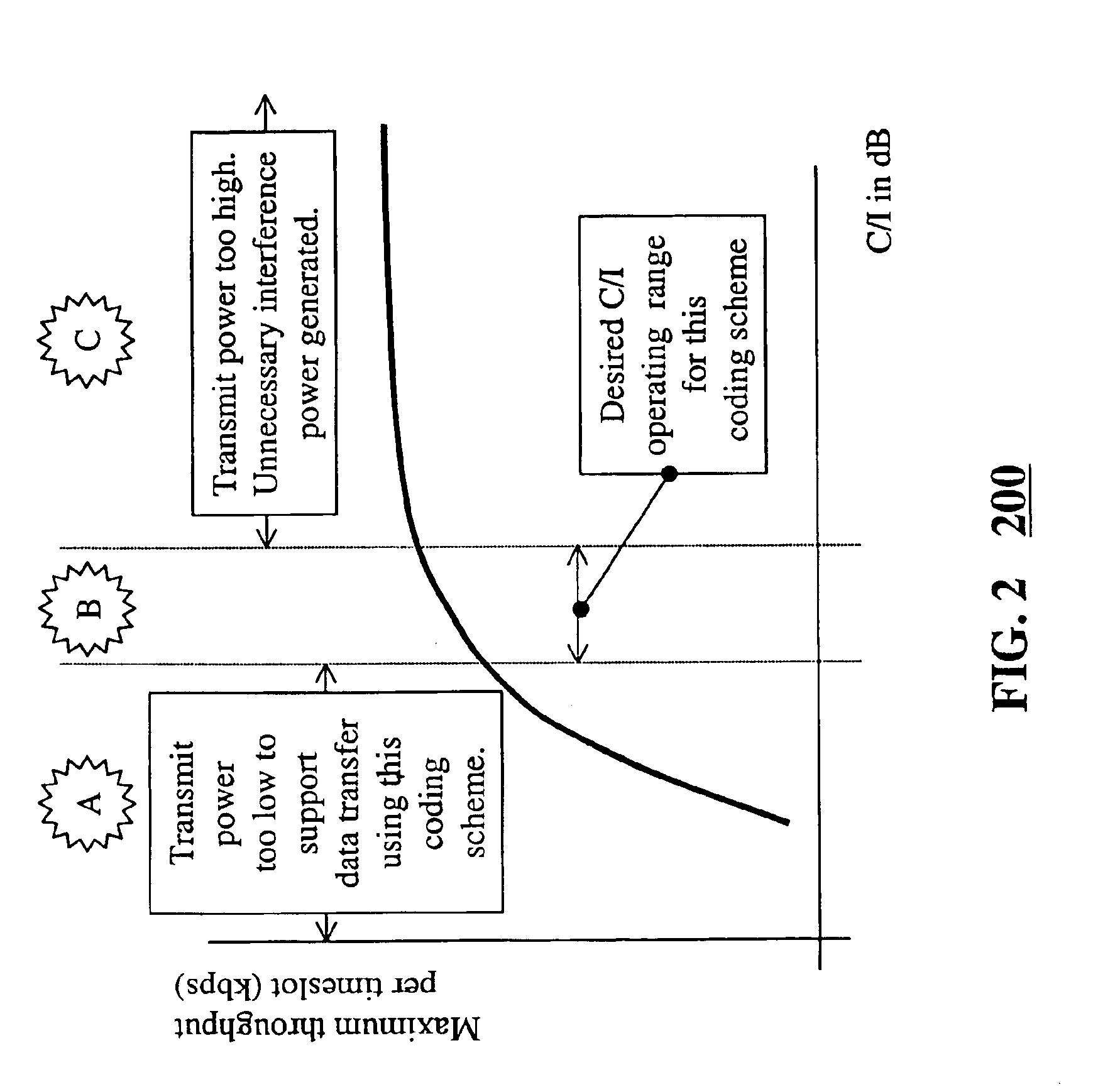
The lower interference levels achieved by power control can result in higher airlink throughputs over larger portions of the cell, potentially increasing a cell's data traffic carrying capacity.
Inadequate power control for circuit-switched calls can lead to dropped calls, service disruptions which are extremely annoying for users and network operators alike.
Inadequate power control for GPRS mobile stations can cause high BLERs, or, at worst, broken TBFs.
Power control errors in GPRS networks increase packet delays and decrease user throughputs, thus causing service degradation rather than wholesale service disruption.

Method used


Image

  • Downlink power control method for wireless packet data network
  • Downlink power control method for wireless packet data network
  • Downlink power control method for wireless packet data network

Examples


Embodiment Construction

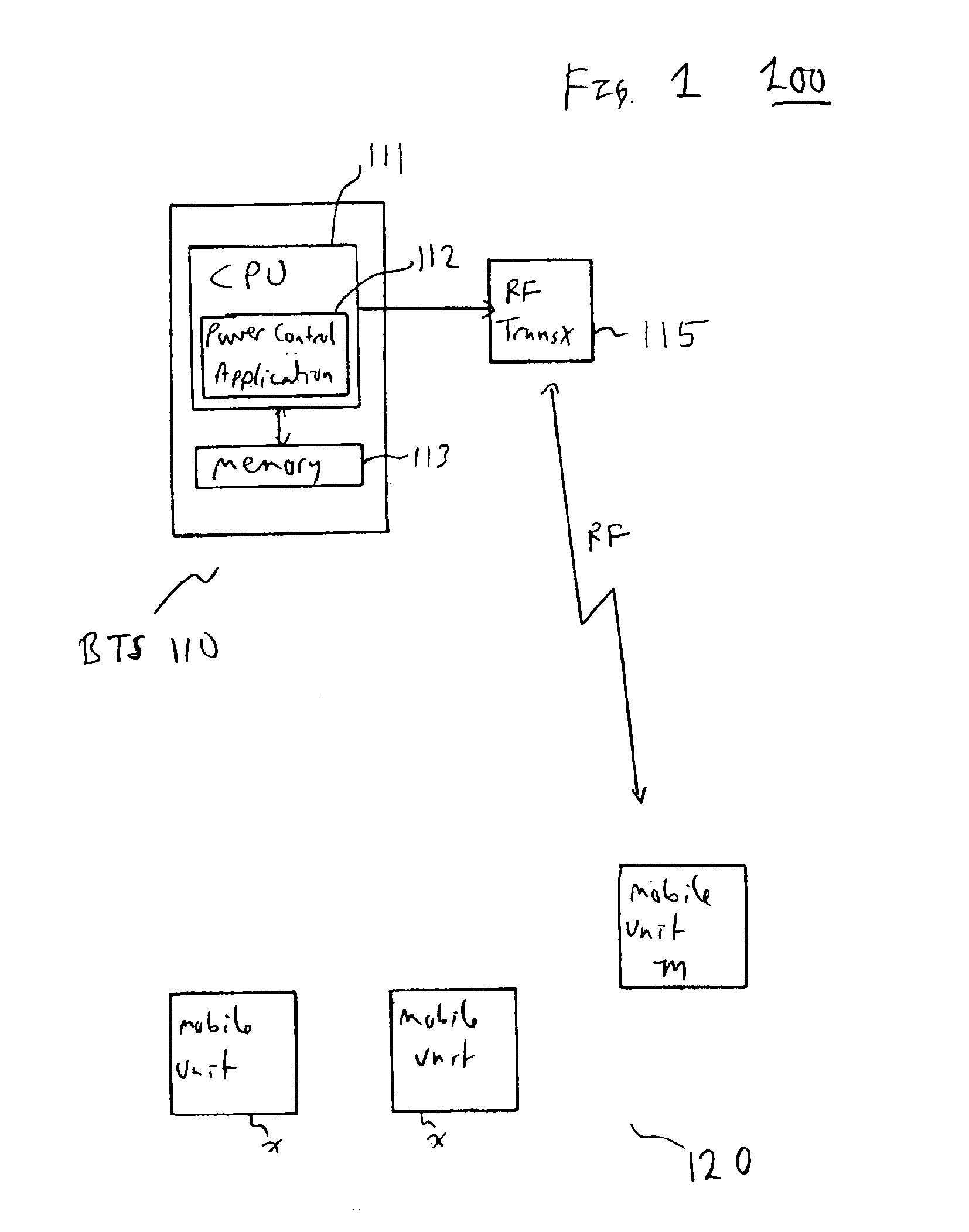
In the present invention, a GPRS downlink power control method or algorithm is provided to control the power used for downlink transmissions of each block. The GPRS downlink power control method of the present invention operates, in a preferred embodiment, within the GPRS power control framework outlined in the ETSI GPRS 05.08 system specification, described above. In an embodiment, a group of blocks is transmitted between polling or measurement intervals. The last block polls the mobile station for airlink quality. This airlink quality measurement reported by the mobile is an average of the airlink quality of a previous group of blocks. Each block of a group of blocks is transmitted at a potentially different power level, however. The downlink power control method of the present invention determines an initial or baseline power transmission level for blocks of the next group of block, and a potentially different power level for each block of the group of blocks, based on the averag...


PUM


Abstract

In a system having a base station transmitter for transmitting data blocks to one or more mobile stations over a radio link, a method for determining a transmit power level at which to transmit a current block. A quality measurement is received from a mobile station indicating an average radio link quality over a previous group of blocks, wherein not all of the blocks of the previous group of blocks were necessarily transmitted at the same transmit power level. A transmit power attenuation level is determined for the current block based on the quality measurement. The transmit power attenuation level is subtracted from the initial transmit power level to determine the transmit power level for the current block.

Description

BACKGROUND OF THE INVENTION1. Field of the InventionThe present invention relates to wireless communications and, in particular, to a technique for determining downlink power used for transmissions from a base station of a system such as the general packet radio service (GPRS) system to one or more mobile stations of the system.2. Description of the Related ArtA variety of wireless communications systems are increasingly being employed. In cellular systems, for example, a network of base transceiver stations (BTSs) are used to provide wireless links with mobile stations or units (e.g., cell phones). The mobile stations, sometimes referred to simply as mobiles, typically communicate via either analog or digital modulated radio frequency (RF) signals with the base station, which is itself connected to an external telephone or data network.A variety of digital cellular networks and telecommunications standards are in use, such as GSM (Global System for Mobile Communication), and GSM de...

Claims


Application Information

Patent Timeline
Patent Type & Authority Patents(United States)
IPC IPC(8): H04B7/005H04W52/00H04W52/02H04W52/20
CPCH04W52/20
Inventor BUDKA, KENNETHMURTI, KAMALADAS, ARNAB
Owner LUCENT TECH INC
Learn More