Impeller blade for axial flow fan having counter-rotating impellers

a technology of axial flow fan and impeller, which is applied in the direction of speed/acceleration/shock measurement device testing/calibration, amplifier modification to reduce noise influence, etc., can solve the problem that the prior art invention does not disclose the use of such optimized blades, and achieve the effect of improving performance parameters, reducing the axial width of the axial flow fan, and increasing air-flow

Inactive Publication Date: 2005-02-15
MINEBEA CO LTD
View PDF52 Cites 13 Cited by
  • Summary
  • Abstract
  • Description
  • Claims
  • Application Information

AI Technical Summary

Benefits of technology

Through experimentation, it has been shown that a fan with counter-rotating impellers employing the improved blade design described herein will provide increases in air-flow as compared to a fan with a single impeller that are substantially greater than the increases predicted by conventional theory. In addition, it has been shown that a fan with counter-rotating impellers employing the improved blade design described herein will provide more than twice the air flow into a pressurized environment as an otherwise identical fan with co-rotating impellers. Accordingly, it is an object of this invention to provide a multiple impeller axial flow fan in which the impellers are substantially coaxial and counter-rotating, with substantially improved performance parameters.
It is an additional object of the invention to provide a blade incorporating a family of airfoil sections capable of reducing the axial width of an axial flow fan while maintaining performance parameters and design constraints.
It is yet another object of the invention to provide a blade incorporating a family of airfoil sections which allow for the reduction of the axial width of an axial fan while locating the maximum work distribution between the root portion and the tip portion of the blade.
It is yet another object of the invention to provide a blade incorporating a family of airfoil sections that allow for the reduction of the overall size of an axial fan while maintaining a favorable velocity profile over the suction side of the blade.

Problems solved by technology

In addition, no invention in the prior art discloses the use of such optimized blades in making dual impeller, coaxial, counter-rotating fan.

Method used


Image

  • Impeller blade for axial flow fan having counter-rotating impellers
  • Impeller blade for axial flow fan having counter-rotating impellers
  • Impeller blade for axial flow fan having counter-rotating impellers

Examples


Embodiment Construction

General Structure of the Axial Flow Fan

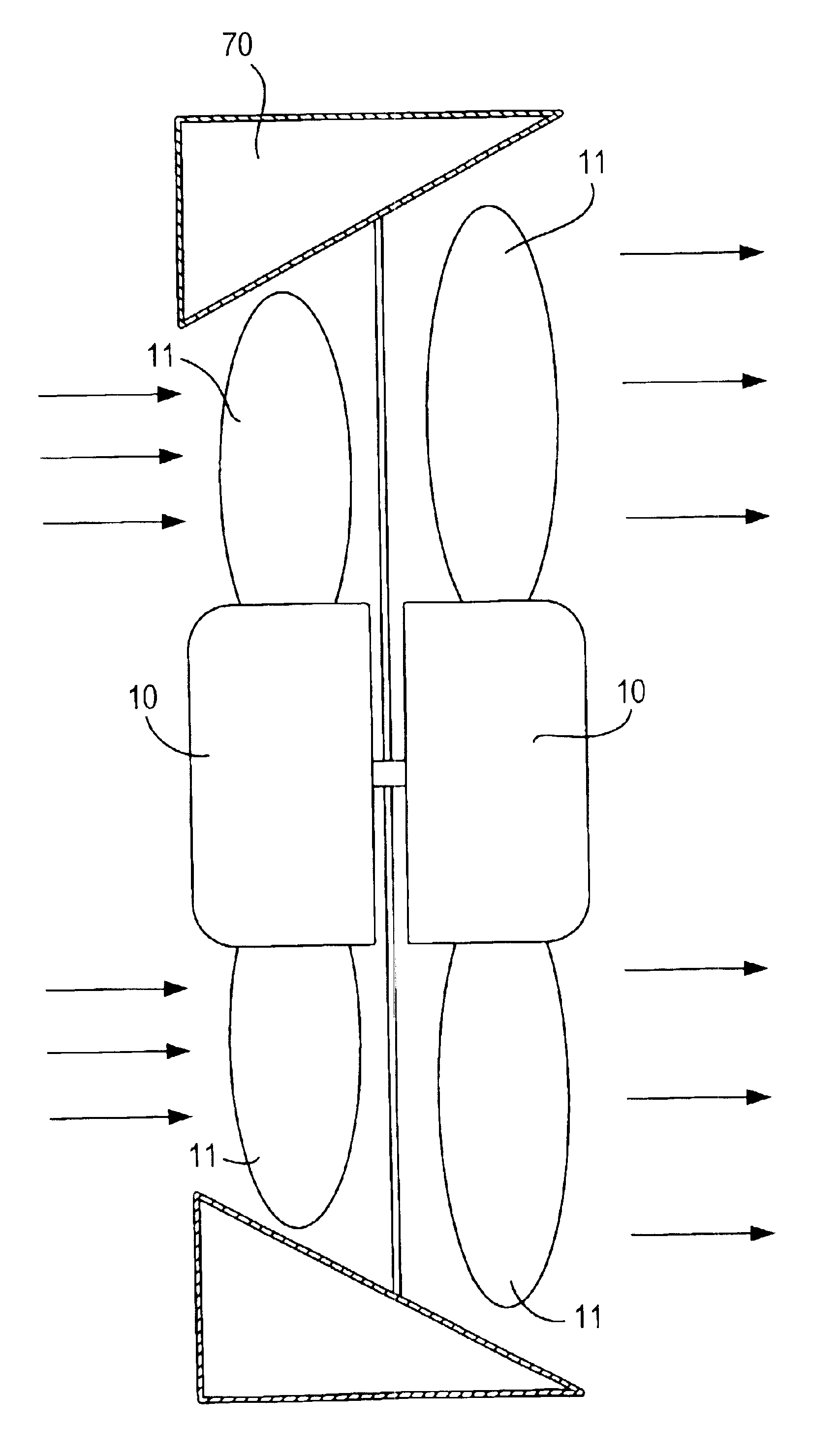
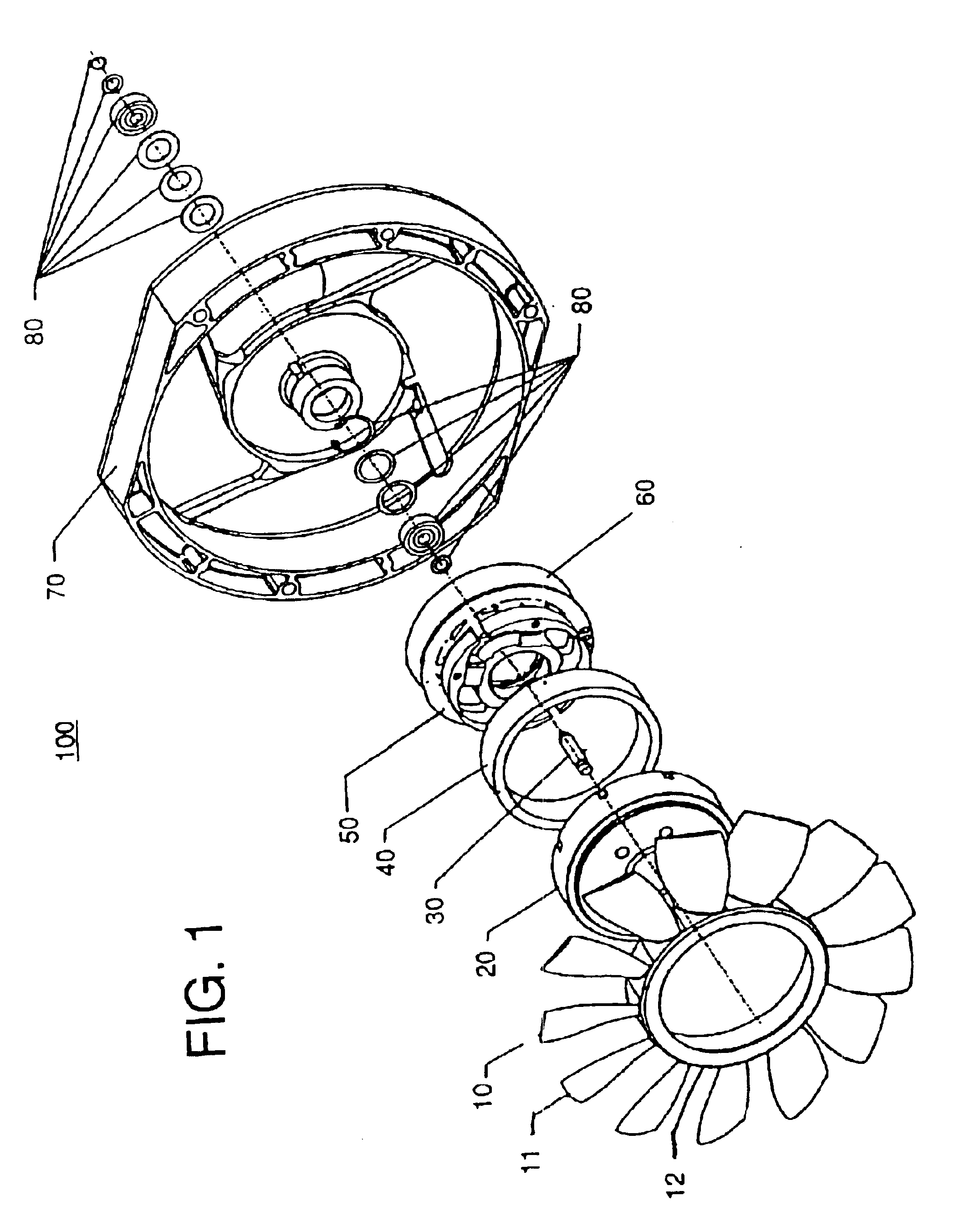
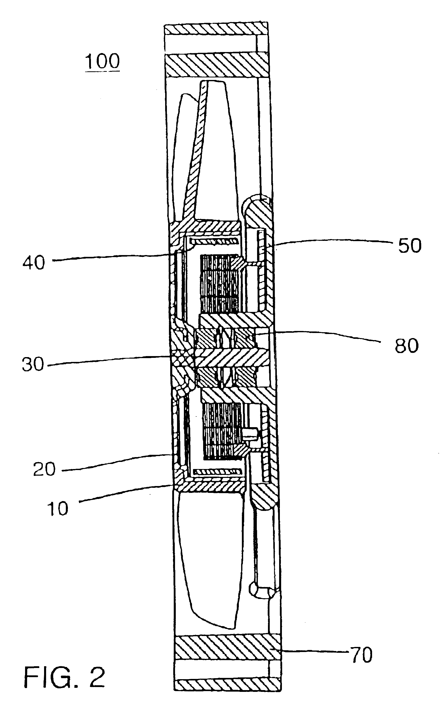
A description of a preferred embodiment of the present invention will now be given. Referring now to the drawings, and in particular to FIGS. 1 and 2, wherein illustrated is an axial flow fan 100, comprising an impeller 10, for generating air flow when rotated, a yoke 20 mounted in impeller 10, a shaft 30 coupled to yoke 20, a permanent magnet 40 mounted in yoke 20, a stator assembly 50, a fan housing 70, an insulation sheet 60 for electrically insulating the base within stator assembly 50 from fan housing 70, and bearings and mounting hardware 80 which serve to secure the shaft 30 to housing 70 while allowing yoke 20 and magnet 40 to freely rotate, thereby rotating impeller 10. The impeller 10 comprises a plurality of blades 11 equally spaced and circumferentially mounted on circular band 12. The permanent magnet 40 mounted in yoke 20, when combined with stator assembly 50, forms an electrical motor which turns impeller 10 when a voltage is ap...


PUM


Abstract

Method for determining the camber line and thickness distribution for blades used in a cooling fan with counter-rotating impellers. The camber lines and thickness distributions for the blades of each of the impellers are determined through use of Bezier curves and chosen to reduce boundary layer separation of airflow across the blades. The Bezier control points are altered to produce a set of distributions of the camber lines and thickness distributions, and the most favorable set is found with increased cooling efficiency.

Description

FIELD OF THE INVENTIONThe present invention relates to an axial flow fan, and more particularly to a multiple impeller arrangement with coaxial impellers that rotate in opposite directions. The multiple impeller counter-rotating axial flow fan of the present invention is especially suitable for use in cooling electronic components.BACKGROUND OF THE INVENTIONA conventional axial flow fan is generally composed of a driving motor, a cylindrical central hub section mounted on a motor shaft attached to the driving motor, a plurality of blades affixed to the hub, and a housing for encasing the fan or impeller, used herein as equivalent terms. Each of the blades extends radially outward from the central hub section of the fan. The motor shaft is attached to the hub section at a central aperture and thus the hub section may be rotated by the driving motor via the motor shaft. In such an arrangement, the hub section together with the blades are rotated by the motor about an axis of the outer...

Claims


Application Information

Patent Timeline
Patent Type & Authority Patents(United States)
IPC IPC(8): F04D29/38H02K11/04H02K29/00H02K7/14
CPCF04D29/384H02K11/0073H02K29/00H02K7/14H02K11/33F04D19/007F04D19/024
Inventor BRADBURY, PHILLIP JAMESNGUYEN, PHEP XUANJENKINS, CHALMERS R.FRANKEL, SCOTT H.
Owner MINEBEA CO LTD
Why Eureka
Try Eureka