I/O node for a computer system including an integrated graphics engine and an integrated I/O hub

a computer system and graphics engine technology, applied in computing, instruments, electric digital data processing, etc., can solve the problems of reducing signal bandwidth, reducing signal integrity, and many bus systems suffering from several drawbacks

Inactive Publication Date: 2005-02-15
GLOBALFOUNDRIES US INC
View PDF16 Cites 7 Cited by
  • Summary
  • Abstract
  • Description
  • Claims
  • Application Information

AI Technical Summary

Problems solved by technology

Unfortunately, many bus systems suffer from several drawbacks.
In addition, the multiple attach points on a shared bus produce signal reflections at high signal frequencies which reduce signal integrity.
The relatively low signal frequencies reduce signal bandwidth, limiting the performance of devices attached to the bus.
Lack of scalability to larger numbers of devices is another disadvantage of shared bus systems.
Once the bandwidth requirements of the devices attached to the bus (either directly or indirectly) exceeds the available bandwidth of the bus, devices will frequently be stalled when attempting access to the bus, and overall performance of the computer system including the shared bus will most likely be reduced.
In addition, those I / O devices may have bandwidth requirements that may cause other devices connected to the PCI-X bus to be unintentionally starved or vice versa.

Method used


Image

  • I/O node for a computer system including an integrated graphics engine and an integrated I/O hub
  • I/O node for a computer system including an integrated graphics engine and an integrated I/O hub
  • I/O node for a computer system including an integrated graphics engine and an integrated I/O hub

Examples


second embodiment

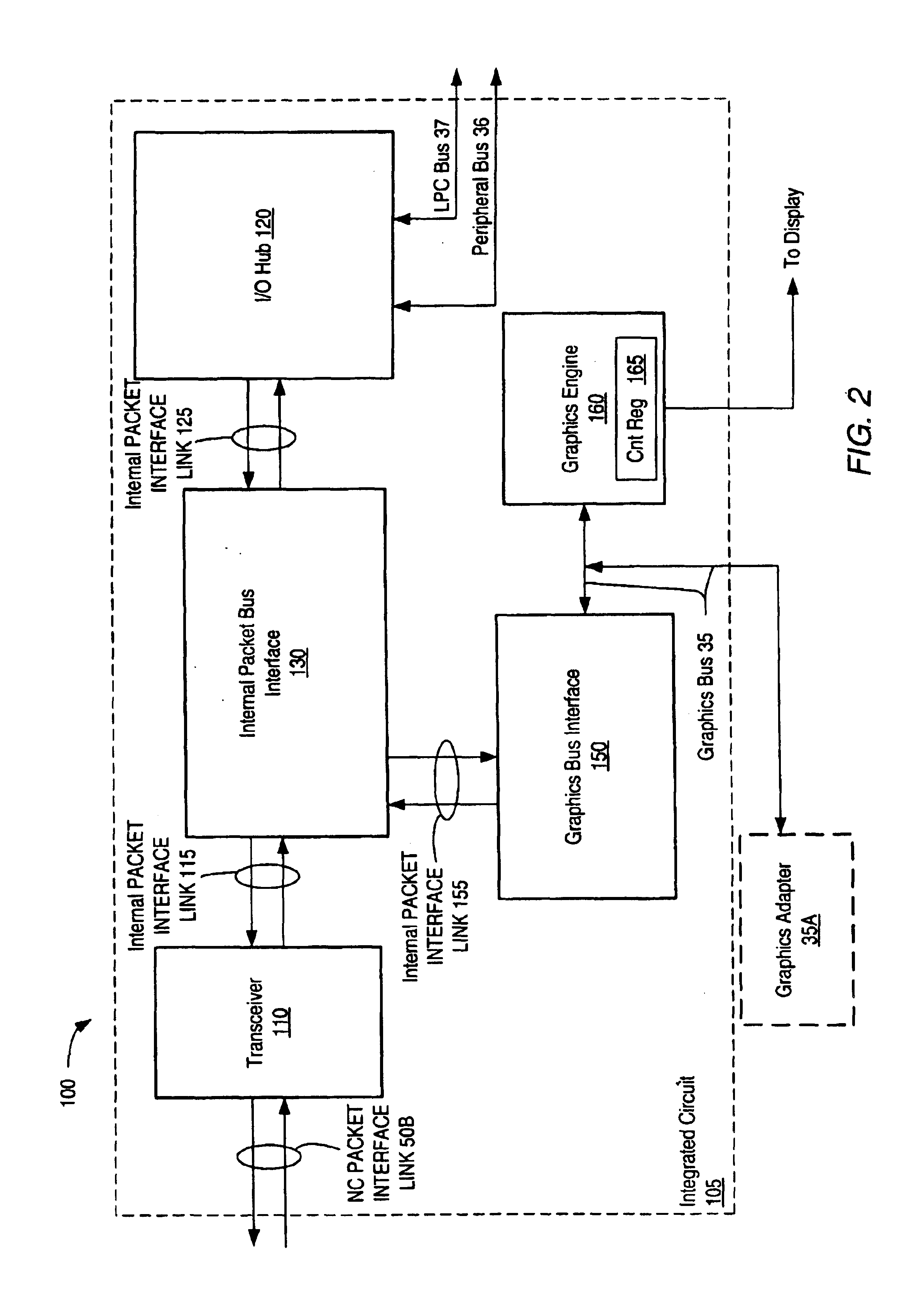
Turning to FIG. 3, a block diagram of second embodiment of an I / O node is shown. Circuit components that correspond to those shown in FIG. 1 and FIG. 2 are numbered identically for simplicity and clarity. I / O node 200 is implemented on a single integrated circuit chip 205. I / O node 200 includes a transceiver unit 210 which is coupled to NC packet interface link 50B and to an internal packet bus interface 230 via an internal packet interface link 215. I / O node 200 also includes an I / O hub 220 which is coupled to internal packet bus interface 230 via an internal packet interface link 225. I / O hub 220 is also coupled to peripheral bus 36 and to LPC bus 37. 10 node 200 further includes a graphics bus interface 250 which is coupled to a graphics bus 35. Graphics bus interface 250 is coupled to receive transactions from transceiver unit 210 through internal packet bus interface 230 and internal packet interface link 255. Graphics engine 260 is also coupled to internal packet bus interface...

third embodiment

Referring to FIG. 4, a block diagram of an I / O node is shown. Circuit components that correspond to those shown in FIG. 1 through FIG. 3 are numbered identically for simplicity and clarity. I / O node 300 is implemented on a single integrated circuit chip 305. I / O node 300 includes a transceiver unit 310 which is coupled to a link of NC packet interface 50B and to an internal packet bus interface 330 via an internal packet interface link 315. I / O node 300 also includes an I / O interface 325 which is coupled to internal packet bus interface 330 via an internal packet interface link 335. I / O interface 325 is coupled to an I / O hub 320 via an interface bus 327. I / O hub 320 is coupled to peripheral bus 36 and to LPC bus 37. I / O node 300 further includes a graphics bus interface 350 which is coupled to an integrated graphics engine 360 through graphics bus 35. Graphics bus interface 350 is coupled to receive transactions from transceiver unit 310 through internal packet bus interface 330 and...

fourth embodiment

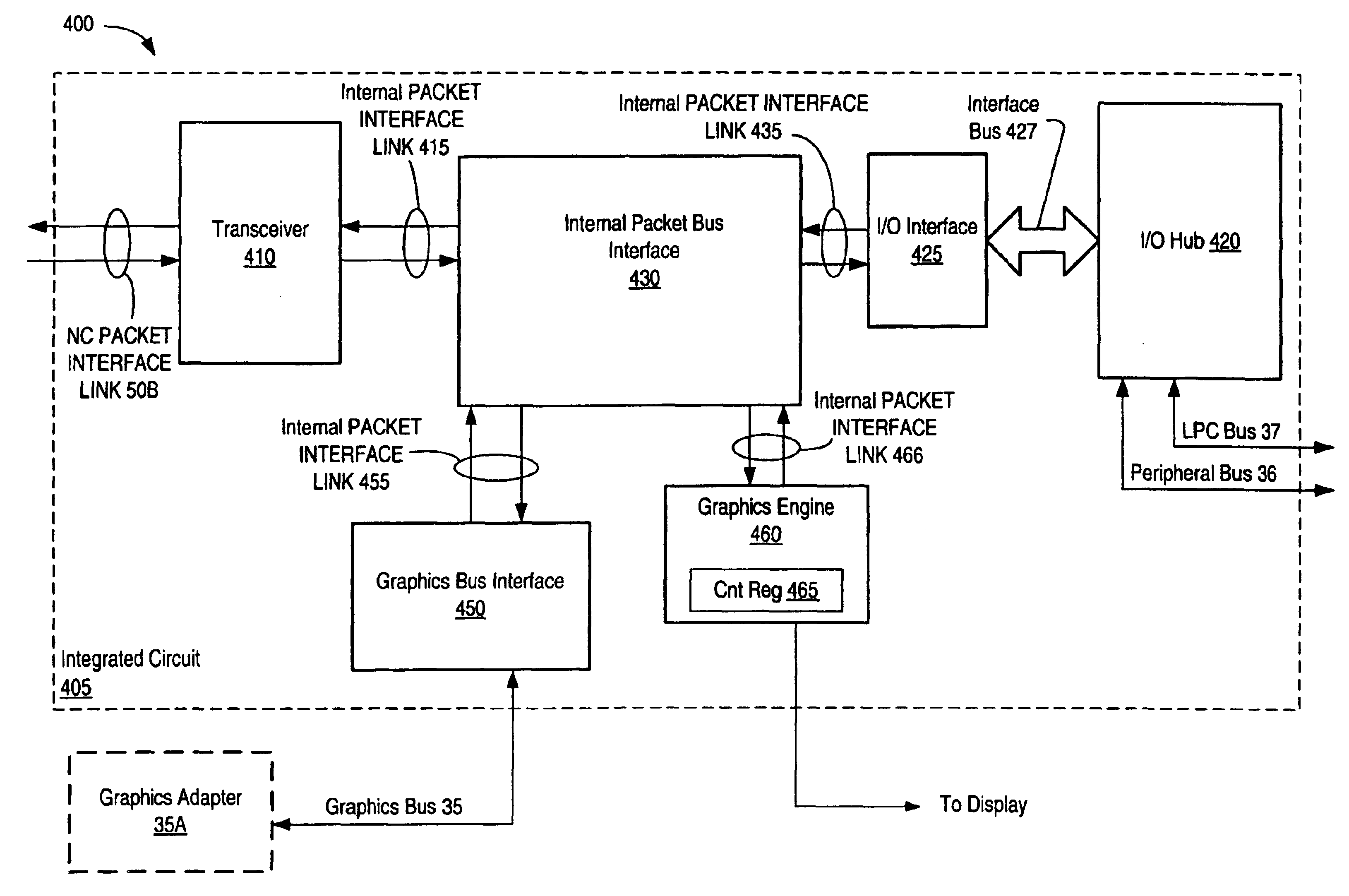
Turning now to FIG. 5, a block diagram illustrating an I / O node is shown. Circuit components that correspond to those shown in FIG. 1 through FIG. 4 are numbered identically for simplicity and clarity. I / O node 400 is implemented on a single integrated circuit chip 405. I / O node 400 includes a transceiver unit 410 which is coupled to a link of NC packet interface 50B and to an internal packet bus interface 430 via an internal packet interface link 415. I / O node 400 also includes an I / O interface 425 which is coupled to internal packet bus interface 330 via an internal packet interface link 435. I / O interface 425 is coupled to an I / O hub 320 via an interface bus 427. I / O hub 420 is coupled to peripheral bus 36 and to LPC bus 37. I / O node 400 further includes a graphics bus interface 450 which is coupled to a graphics bus 35. Graphics bus interface 450 is coupled to receive transactions from transceiver unit 410 through internal packet bus interface 430. Graphics engine 460 is also co...


PUM


Abstract

An I / O node for a computer system including an integrated graphics engine and integrated I / O hub. An input / output node that is implemented on an integrated circuit chip includes a transceiver unit, a graphics engine and an I / O hub. The transceiver unit may receive and transmit packets on a point-to-point link of a packet interface. The graphics engine may be coupled to receive graphics packets received by the transceiver unit and may render digital image information in response to receiving the graphics packets. The I / O hub may be coupled to receive I / O packets corresponding to packets received by the transceiver unit and may initiate bus cycles corresponding to the I / O packets upon a peripheral bus. The packet interface link may be a point-to-point HyperTransport™ link including a first and second set of uni-directional wires which may convey control and data packets over the same wires.

Description

BACKGROUND OF THE INVENTION1. Field of the InventionThis invention relates to computer system input / output (I / O) and, more particularly, to I / O and graphics functionality.2. Description of the Related ArtIn a typical computer system, one or more processors may communicate with input / output (I / O) devices over one or more buses. The I / O devices may be coupled to the processors through an I / O bridge which manages the transfer of information between a peripheral bus connected to the I / O devices and a shared bus connected to the processors. Additionally, the I / O bridge may manage the transfer of information between a system memory and the I / O devices or the system memory and the processors.Unfortunately, many bus systems suffer from several drawbacks. For example, multiple devices attached to a bus may present a relatively large electrical capacitance to devices driving signals on the bus. In addition, the multiple attach points on a shared bus produce signal reflections at high signal f...

Claims


Application Information

Patent Timeline
Patent Type & Authority Patents(United States)
IPC IPC(8): G06F13/38G06F3/14G06F13/42
CPCG06F13/4265G06F3/14
Inventor GULICK, DALE E.HEWITT, LARRY D.MERGARD, JAMES
Owner GLOBALFOUNDRIES US INC
Why Eureka
Try Eureka