Arrangement for clamping a saw blade

a clamping arrangement and saw blade technology, applied in the direction of metal sawing devices, metal sawing apparatus, manufacturing tools, etc., can solve the problems of constant changing the saw blade, warping or snapping of the blade during use, and the loose working of the blade from its mounting position

Inactive Publication Date: 2005-02-22
BLACK & DECKER INC
View PDF21 Cites 19 Cited by
  • Summary
  • Abstract
  • Description
  • Claims
  • Application Information

AI Technical Summary

Benefits of technology

It is thus an object of the present invention to provide an arrangement for clamping a saw blade to a reciprocable shaft, the shaft including a retaining member on which a blade for clamping may be mounted; the retaining member being lockable in at least two positions, each of the at least two positions clamping the blade at a predetermined angle relative to the shaft. The provision of a lockable retaining member allows rapid interchange of different types of saw blade and also allows rigid clamping of the saw blade to the shaft.

Problems solved by technology

Failure to clamp the blade could result in the blade working loose from its mounting and warping or snapping during use.
However, the desire to rigidly clamp the saw blade to its driving shaft tends to create problems with the need to change saw blades depending upon the nature of the workpiece being sawed.
Thus the need to constantly change the saw blade is not helped by the need to rigidly mount the blade on its driving shaft.

Method used


Image

  • Arrangement for clamping a saw blade
  • Arrangement for clamping a saw blade
  • Arrangement for clamping a saw blade

Examples


Embodiment Construction

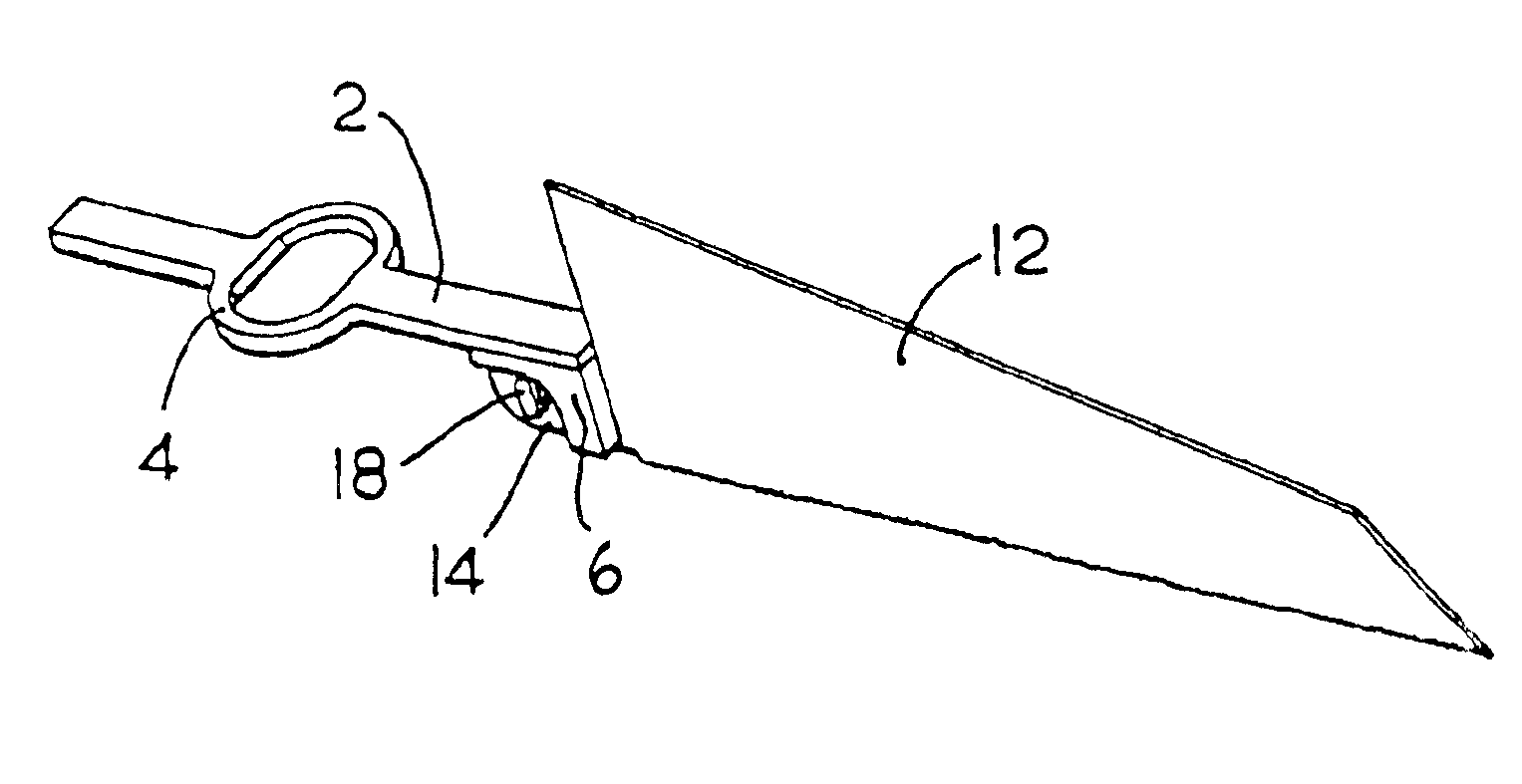
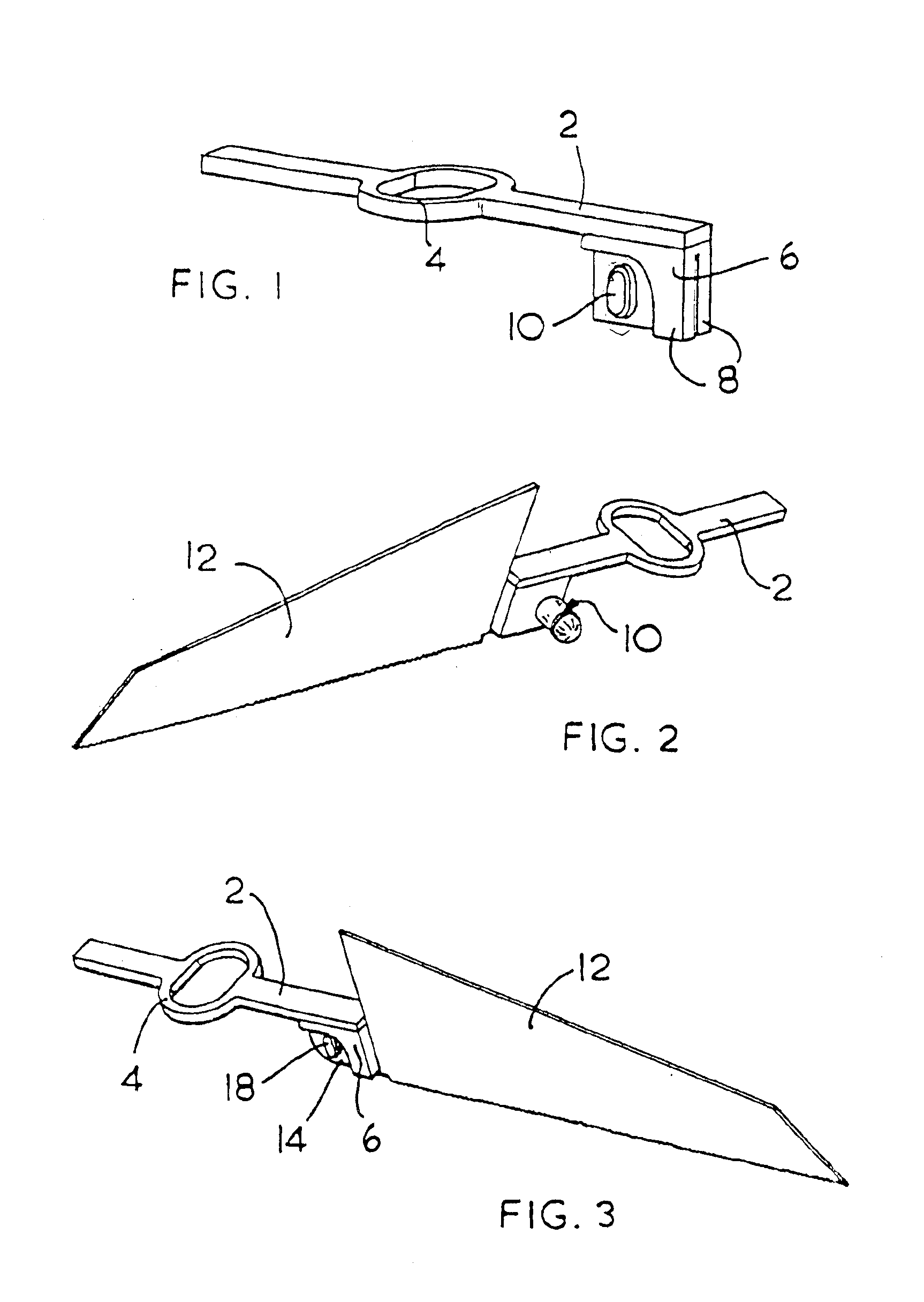
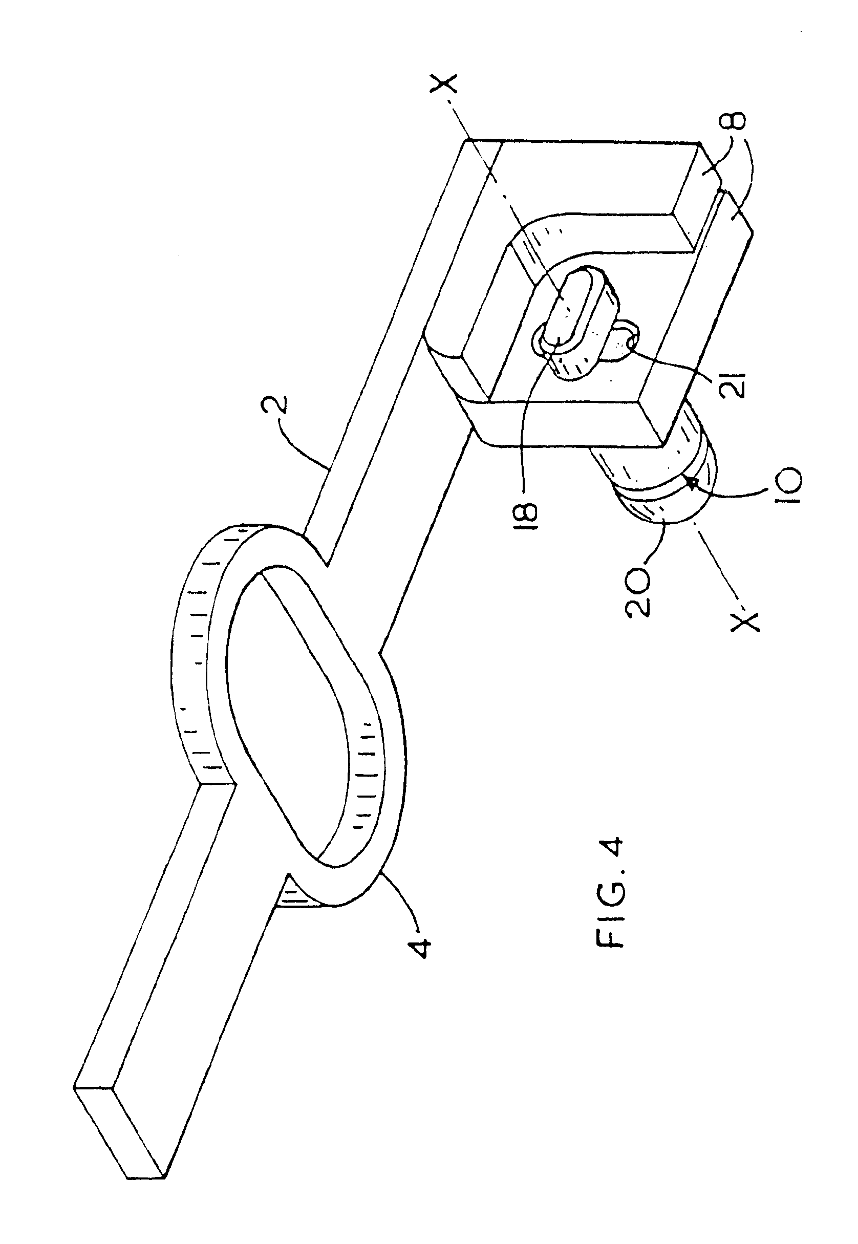
Referring firstly to FIG. 1, there is shown a shaft (2) formed from pressed metal, such as steel, and having in the centre thereof a yoke (4). One end of the shaft (2) is formed integrally with a depending retaining member, here a blade mount (6). The blade mount (6) comprises a restraining means, here two arms (8) which depend from the shaft (2). The blade mount further includes a pin (10) which will be described in more detail below.

Referring now also to FIGS. 2 and 3, it can be seen that the shaft (2) is arranged to drive a saw blade (12) presented thereto and which is mounted on the blade mount (6). It can be seen that the saw blade (12) has a shank (14) which has formed therein a hole (16) (seen more clearly in FIGS. 5, 8 and 9) for mounting the blade (12) on a lug (18) of the pin (10). Although the saw blade (12) includes a shank in this, preferred, embodiment, the shank may be formed integrally with the body portion, as discussed below and with reference to FIG. 14(b).

Referri...


PUM

PropertyMeasurementUnit
lengthaaaaaaaaaa
stroke lengthaaaaaaaaaa
angleaaaaaaaaaa

Abstract

An arrangement for clamping a saw blade (12) includes a retaining member (6) on which a blade (12) for clamping can be mounted. The retaining member (6) is lockable in at least two positions such that each of the two positions clamps the blade (12) at a predetermined angle relative to a shaft (2) which drives the saw blade (12).

Description

BACKGROUND OF THE INVENTIONThe present invention relates to an arrangement for clamping a saw blade and to a saw blade for use with the clamping arrangement and has particular, although not exclusive, relevance to such a clamping arrangement as used on a power jigsaw, or the like.The ability to clamp the blade of a power saw has long been known to be a desirable feature. Power saws which cut using a linear reciprocal action usually operate at high stroke speeds, such as 3,000 strokes per minute.Because of the large forces generated by the cutting action at these reciprocal frequencies, there is a need to rigidly clamp the blade to the shaft on which it is mounted and which is being driven by the motor of the power saw. Failure to clamp the blade could result in the blade working loose from its mounting and warping or snapping during use.However, the desire to rigidly clamp the saw blade to its driving shaft tends to create problems with the need to change saw blades depending upon t...

Claims


Application Information

Patent Timeline
Patent Type & Authority Patents(United States)
IPC IPC(8): B23D51/10B23D51/00
CPCB23D51/10Y10T83/9483
Inventor MASON, NEIL
Owner BLACK & DECKER INC
Why Eureka
Try Eureka