
Two-stroke engine

a two-stroke engine technology, applied in the direction of combustion engines, machines/engines, charge feed systems, etc., can solve the problems of unoptimized air/fuel ratio in the combustion chamber for the entire operating rpm range, and achieve good dynamic performance

Inactive Publication Date: 2005-02-22
ANDREAS STIHL AG & CO KG
View PDF3 Cites 24 Cited by
  • Summary
  • Abstract
  • Description
  • Claims
  • Application Information

AI Technical Summary

Benefits of technology

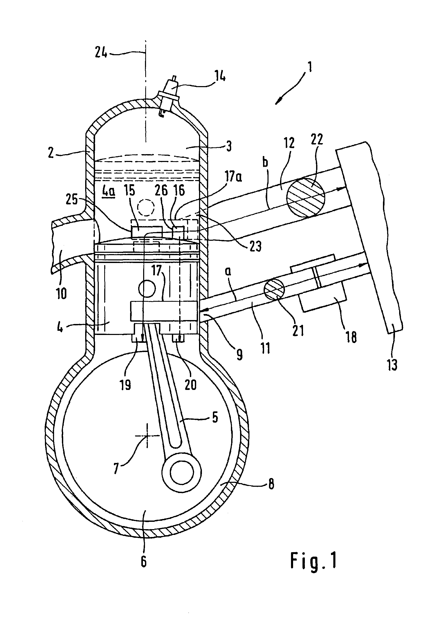
A good dynamic performance of the two-stroke engine results when the length of the intake channel from the air filter to the inlet into the crankcase amounts only to approximately 60% of the length of the clean air path. The length of the clean air path is the mean channel length from the air filter to the entry opening of the transfer channels into the crankcase. By configuring the intake channel shorter than the clean air path, there results furthermore a favorable structural configuration. Air channel and intake channel can be connected especially to an air filter.
wherein:c is the sonic velocity; A is the resistance-relevant area; L is the length and V is the crankcase volume. The clean air path and mixture path are thereby matched to the same frequency characteristic. The two-stroke engine therefore has a good dynamic performance.

Problems solved by technology

Since the mixture path should be approximately as long as the air path, unfavorable spatial conditions result because the mixture path must be configured comparatively long compared to the portion of the air path lying outside of the cylinder.
Here, it has been shown that the air / fuel ratio in the combustion chamber is not optimal for the entire operating rpm range for air and mixture channels having approximately the same length.

Method used


Image

  • Two-stroke engine
  • Two-stroke engine
  • Two-stroke engine

Examples


Embodiment Construction

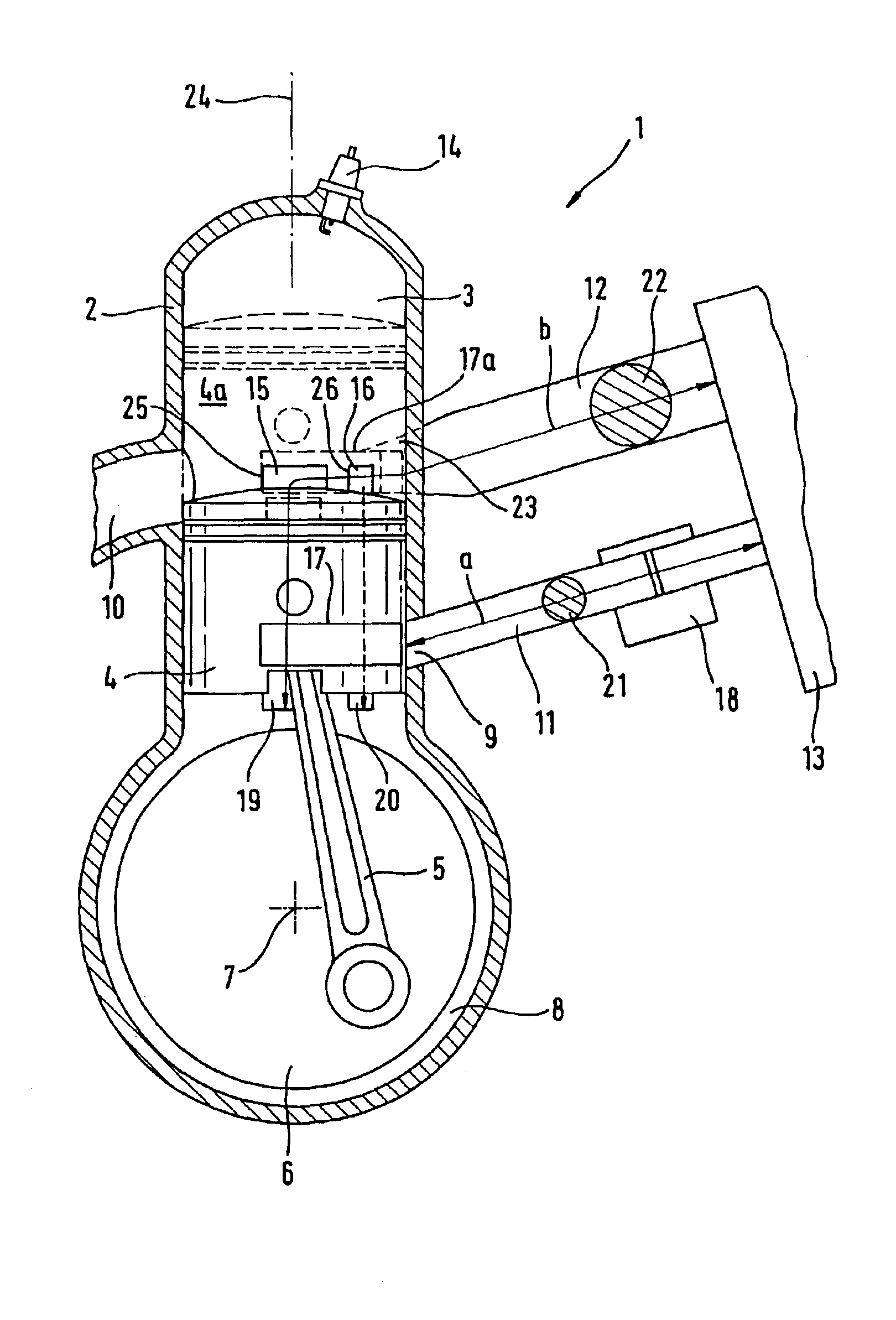
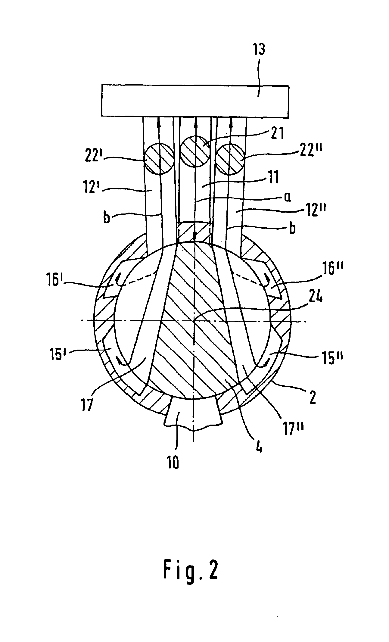
The two-stroke engine 1 shown in FIG. 1 includes a cylinder 2 having a cylinder longitudinal axis 24 and a combustion chamber 3 configured in the cylinder 2. The combustion chamber 3 is delimited by an upwardly and downwardly moving piston 4 which is shown with broken lines in its upper position 4a close to top dead center (TDC). The piston 4 drives a crankshaft 6 via a connecting rod 5 and the crankshaft 6 is journalled in the crankcase 8 so as to be rotatable about the crankshaft axis 7. An air / fuel mixture is supplied to the crankcase 8 from the intake channel 11 through the inlet 9. The intake channel 11 is connected to an air filter 13 and is formed in a carburetor 18 over a segment of its length. The two-stroke engine 1 includes overall four transfer channels 15 and 16, which are arranged symmetrically to a center plane. Two transfer channels 15 are arranged to be outlet near and two transfer channels 16 are arranged to be outlet remote. The transfer channels (15, 16) open wit...


PUM


Abstract

A two-stroke engine, (1) is disclosed which includes (I) transfer channels (15, 15′, 15″, 16, 16′, 16″) which open into the crankcase (8) and fluidly connect the crankcase (8) to the combustion chamber (3) at specific positions of the piston (4) and (ii) an intake channel (11) for supplying an air / fuel mixture into the crankcase (8) via an inlet (9) and is connected to an air filter (13). At least one air channel (12) supplies additional combustion air into at least one transfer channel (15, 15′, 15″, 16, 16′, 16″). For a good load-independent air / fuel mixture ratio, the length (a) of the intake channel (11) is up to 60% of the length (b) of the clean air path; and, length (b) is the mean channel length from the air filter (13) to the opening (19, 20) of a transfer channel (15, 16) into the crankcase (8).

Description

BACKGROUND OF THE INVENTIONU.S. Pat. No. 6,668,770, it is known to configure air path and mixture path approximately the same length. The length of the mixture path should lie between 0.6 times and 1.4 times the length of the air path. In this way, air path and mixture path are to be matched to each other in order to maintain the air / fuel ratio constant, independent of load fluctuations.The air path includes the length of the transfer channels. Since the mixture path should be approximately as long as the air path, unfavorable spatial conditions result because the mixture path must be configured comparatively long compared to the portion of the air path lying outside of the cylinder. Here, it has been shown that the air / fuel ratio in the combustion chamber is not optimal for the entire operating rpm range for air and mixture channels having approximately the same length.SUMMARY OF THE INVENTIONIt is an object of the invention to provide a two-stroke engine which has a favorable air / ...

Claims


Application Information

Patent Timeline
Patent Type & Authority Patents(United States)
IPC IPC(8): F02B25/14F02B33/04F02M23/03F02B25/00F02B33/02F02B25/22F02M23/00F02B63/02F02B63/00F02B1/00F02B1/02F02B75/02
CPCF02B25/14F02B25/22F02B63/02F02M23/03F02B33/04F02B1/02Y02T10/146F02B2075/025Y02T10/12
Inventor SCHLOSSARCZYK, JORGGEYER, WERNER
Owner ANDREAS STIHL AG & CO KG
Learn More