Hydropneumatic pressure reservoir

a technology of hydropneumatic pressure and reservoir, which is applied in the direction of mechanical equipment, rigid containers, transportation and packaging, etc., can solve the problems of contact mismatch, disruption of assembly process, and even damage to the assembly process, so as to avoid disadvantages and simplify assembly

Inactive Publication Date: 2005-02-22
HYDAC TECH GMBH
View PDF6 Cites 45 Cited by
  • Summary
  • Abstract
  • Description
  • Claims
  • Application Information

AI Technical Summary

Benefits of technology

Objects of the present invention are to provide a hydropneumatic pressure reservoir having a construction permitting especially simple assembly and avoiding the disadvantages in conventional hydropneumatic pressure reservoirs, as described above.

Problems solved by technology

Because of the very narrow tolerances, such as must be observed in the case of wall components used in conjunction with each other in the connecting area of the housing shells and of the surfaces coming in contact with the edge area of the diaphragm, installation of the diaphragm and assembly of the housing shells tend to be a relatively difficult process.
Because of the precise fit required, the smallest errors in alignment or inclination relative to the longitudinal axis during assembly of the components result in disruption of the assembly process or even in damage from misalignment or tilting.
If the housing shells come in contact with each other during assembly of the disclosed reservoir, contact mismatch may occur even with precisely worked guide and retaining surfaces.
Such contact mismatch impairs the clamping of the diaphragm and its later fastening in the reservoir, and may also greatly complicate assembly.
Thus, tightness problems may arise especially in the event of inaccurate clamping within the framework of the assembly as described.

Method used


Image

  • Hydropneumatic pressure reservoir
  • Hydropneumatic pressure reservoir
  • Hydropneumatic pressure reservoir

Examples


first embodiment

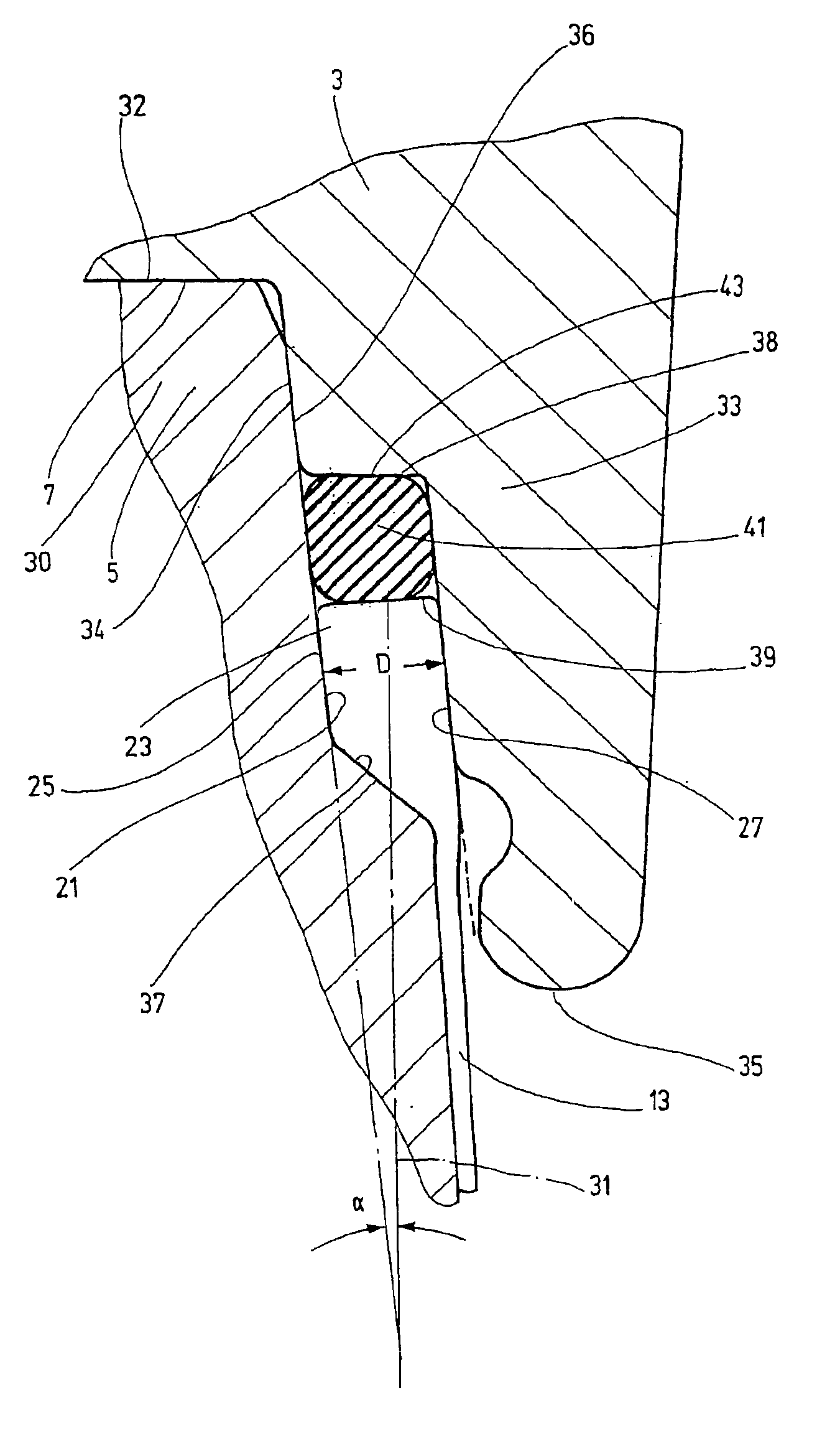
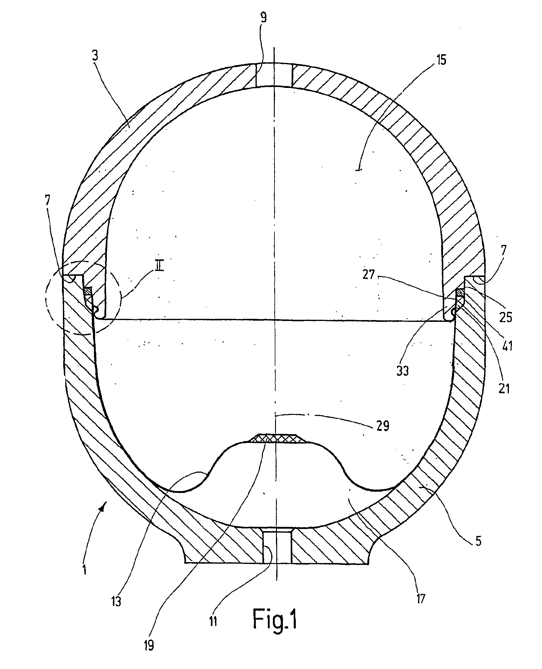
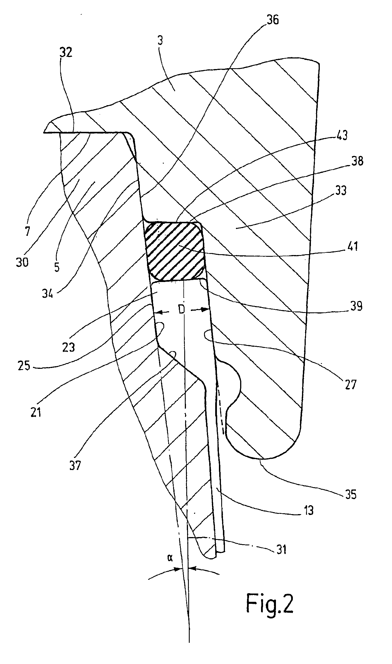
FIG. 2 shows the area designated as II in FIG. 1 on a larger scale so as to present in greater detail the configuration of the edge area 21 of the diaphragm 13 and of the retaining device for clamping the diaphragm 13. In the first embodiment shown in FIGS. 1 and 2, the edge area 21 of the diaphragm 13 has a bead-like thickening 23 seated between two retaining surfaces, a first retaining surface 25 associated with the housing shell 5 and a second retaining surface 27 associated with the housing shell 3. The retaining surfaces 25 and 27 extend over the entire circumference of the pressure reservoir housing equidistant from each other. An annular gap is formed between retaining surfaces 25 and 27 for seating of the edge area 21 of the diaphragm 13. This annular gap is of a constant clear gap width D over its axial extent (FIG. 2).

In FIG. 1, the longitudinal axis 29 of the pressure reservoir 1 is defined by the approximately spherical form of the housing shells 3 and 5. The longitudina...

fourth embodiment

Lastly, FIG. 5 illustrates a In the area identified as IV / V in FIG. 3, sealing elements 61 and 63 are seated in annular grooves on both sides of the folded outward edge of the diaphragm 13. These sealing elements 61 and 63 in turn serve both as additional force storage elements for clamping force generation and as seals. The respective sealing elements are preferably used in pairs, sealing off from the gas side and from the hydraulic side. With an appropriate design of the diaphragm 13, the sealing elements can perform exclusively the function of sealing on the oil side.


PUM


Abstract

A hydropneumatic pressure reservoir (1) forms a housing from at least two housing shells (3, 5) connected together. At least the end region of the one housing shell (5) includes an outwardly-extending, funnel-like guide surface between its free end and a sealing element for bringing together the two housing shells (3, 5). At least on elastic sealing element (41) is provided on at least one retaining surface for generation of a tensioning force on the boundary region (21) of the membrane (13). A simplified construction with improved sealing in the critical connection of the pressure reservoir is achieved.

Description

FIELD OF THE INVENTIONThe present invention relates to a hydropneumatic pressure reservoir having a housing separating the interior of the reservoir from the external environment. This housing comprises at least two housing shells connected to each other, and has a cross-section defining a longitudinal axis. A partition separdtes the interior of the housing into two chambers, a gas chamber and a liquid chamber. The partition is in the form of a gas-tight diaphragm clamped at its circumferential edge area to form a seal with the interior wall of the housing by a retaining device. The retaining device has retaining surfaces which receive the edge area of the diaphragm between them. At least one energy storage element generates tension (clamping) forces between edge area and retaining surfaces. At least one of the retaining surfaces is formed by a wall component of one of the housing shells. The retaining surfaces extending equidistant from each other over the entire area of their surf...

Claims


Application Information

Patent Timeline
Patent Type & Authority Patents(United States)
IPC IPC(8): F15B1/00F15B1/10F15B1/12F15B1/08
CPCF15B1/106F15B1/12F15B1/125F15B2201/205F15B2201/435F15B2201/3156F15B2201/411F15B2201/415F15B2201/3151
Inventor RUPP, GERNOTLEHNERT, MARKUSBALTES, HERBERT
Owner HYDAC TECH GMBH
Why Eureka
Try Eureka