Rotary edging blade system

dging blade technology, which is applied in the field of rotary edging blade systems, can solve the problems of not describing a rotary edging blade system that allows safely and efficiently edging flower beds, and achieves the effects of low manufacturing cost, convenient and efficient manufacturing and marketing, and durable and reliable construction

Inactive Publication Date: 2005-02-22
HAYES JOHNNY
View PDF4 Cites 8 Cited by
  • Summary
  • Abstract
  • Description
  • Claims
  • Application Information

AI Technical Summary

Benefits of technology

It is therefore an object of the present invention to provide a new and improved rotary edging blade system which has all of the advantages of the prior art trimming and edging blades of known designs and configurations and none of the disadvantages.
It is another object of the present invention to provide a new and improved rotary edging blade system which may be easily and efficiently manufactured and marketed.
It is further an object of the present invention to provide a new and improved rotary edging blade system which is of durable and relia

Problems solved by technology

While these devices fulfill their respective, particular objectives and requirements, the aforementioned patents

Method used


Image

  • Rotary edging blade system
  • Rotary edging blade system
  • Rotary edging blade system

Examples


Embodiment Construction

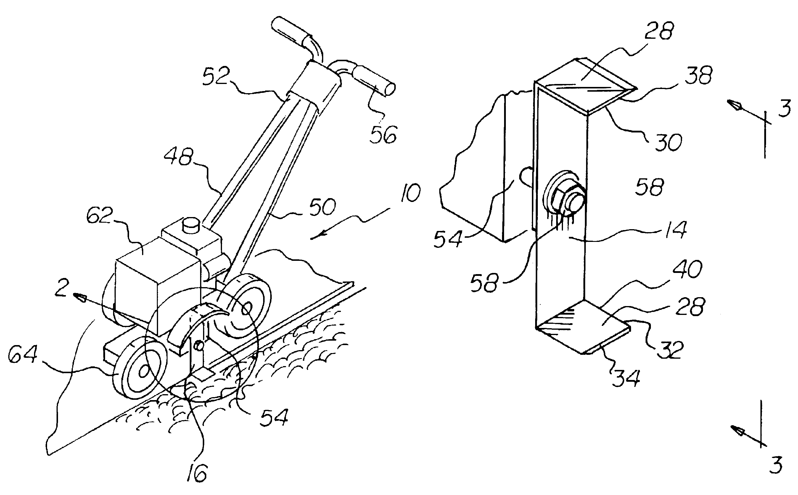
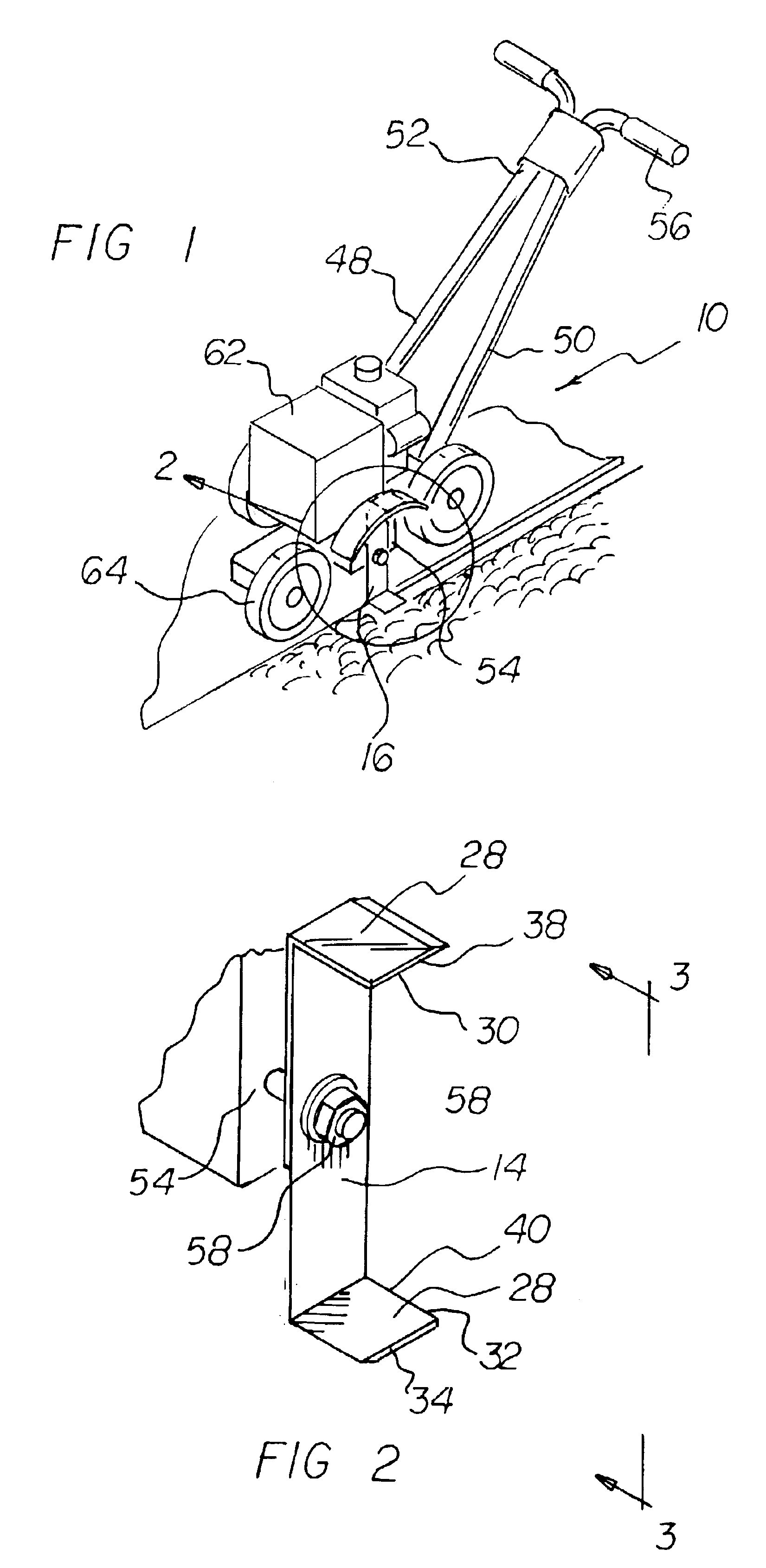
With reference now to the drawings, and in particular to Figure 1 thereof, the preferred embodiment of the new and improved rotary edging blade system embodying the principles and concepts of the present invention and generally designated by the reference numeral 10 will be described.

The present invention, the rotary edging blade system 10 is comprised of a plurality of components. Such components in their broadest context include a blade and a horizontal cutting edge. Such components are individually configured and correlated with respect to each other so as to attain the desired objective.

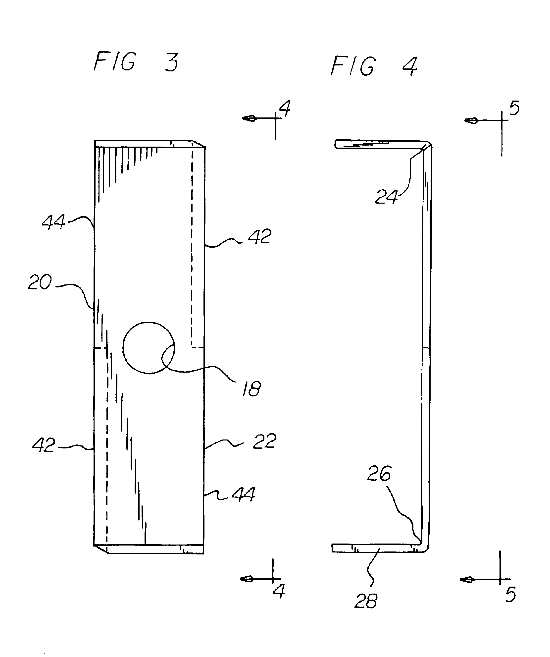
First provided is a blade 14. The blade is fabricated of stainless steel. The blade is in a plate-like configuration. The blade further has a thickness of about 0.125 inches plus or minus 10 percent. The blade is formed of a vertical segment 16. A central circular aperture 18 is provided through the vertical segment. The diameter of the aperture is about 1 inch plus or minus 10 percent. The cente...


PUM


Abstract

A blade is formed of a vertical segment. The vertical segment has a central aperture. The vertical segment further has long parallel side edges, short parallel end edges and upturned parallel ends. Each end has a leading edge and a trailing. A horizontal cutting edge is formed into each leading edge of the upturned parallel ends. A vertical cutting edge is formed into each long edge adjacent to a horizontal cutting edge.

Description

BACKGROUND OF THE INVENTION1. Field of the InventionThe present invention relates to a rotary edging blade system and more particularly pertains to safely and efficiently edging flower beds and the like.2. Description or the Prior ArtThe use of trimming and edging blades of known designs and configurations is known in the prior art. More specifically, trimming and edging blades of known designs and configurations previously devised and utilized for the purpose of edging grassy areas and the like by conventional methods and apparatuses are known to consist basically of familiar, expected, and obvious structural configurations, notwithstanding the myriad of designs encompassed by the crowded prior art which has been developed for the fulfillment of countless objectives and requirements. By way of example, U.S. Pat. No. Des. 221,483 to Terwilliger discloses a lawn trimmer blade for sprinkled heads. U.S. Pat. No. 3,395,521 to Crockett discloses a thatch remover attachment for rotary law...

Claims


Application Information

Patent Timeline
IPC IPC(8): A01G3/00A01G3/06
CPCA01G3/062
Inventor HAYES, JOHNNY
Owner HAYES JOHNNY
Why Eureka
Try Eureka