
Worm shaft attachment structure for spinning reel

a technology of worm shaft and attachment structure, which is applied in the field of worm shaft attachment structure, can solve the problems of difficult to ensure the difficult to maintain and difficult to form the concave hole and the through hole concentrically with high precision, so as to achieve the effect of reducing the restriction on design options and ensuring the attachment precision of the worm sha

Inactive Publication Date: 2005-02-22
SHIMANO INC
View PDF9 Cites 5 Cited by
  • Summary
  • Abstract
  • Description
  • Claims
  • Application Information

AI Technical Summary

Benefits of technology

It is thus a purpose of the present invention to provide a worm shaft attachment structure for a spinning reel, in which the attachment precision of the worm shaft can be ensured easily, and restrictions on the design options are reduced.
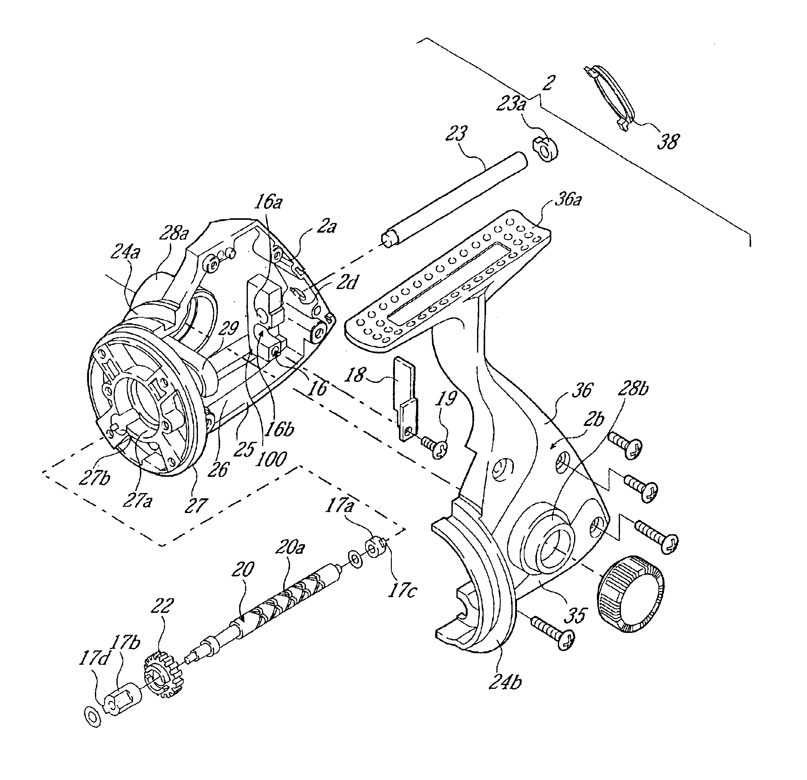
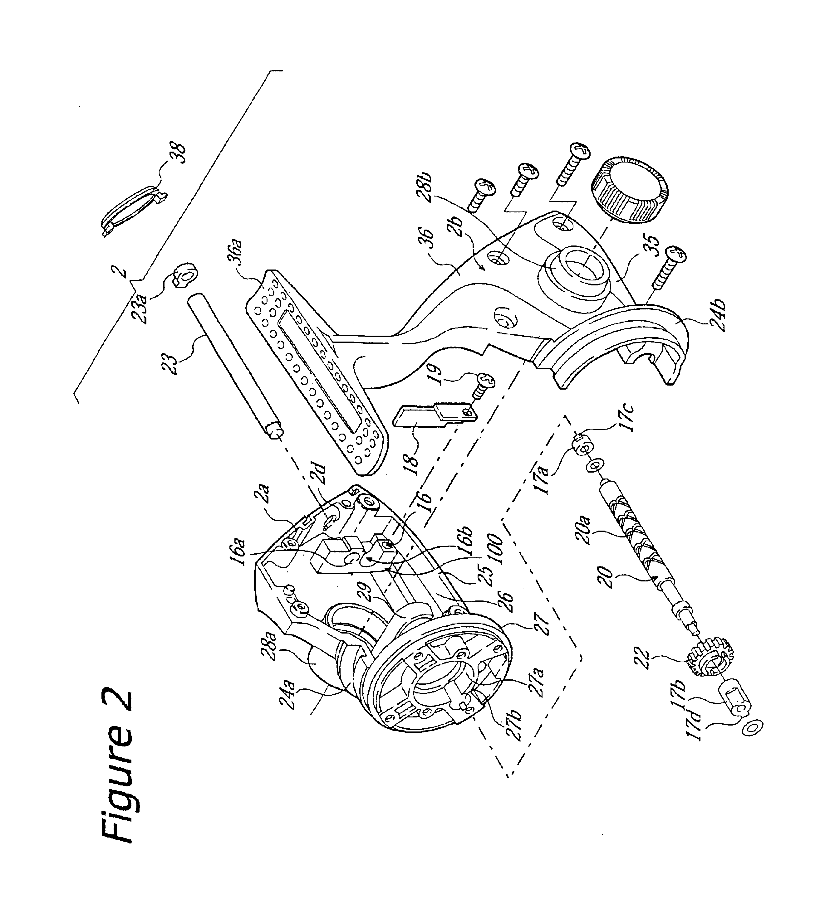
A worm shaft attachment structure for a spinning reel according to a first aspect of the present invention is a structure in which a worm shaft is attached rotatably to a reel unit via a first and a second bearing that are disposed at two ends of the worm shaft. Intersecting helical grooves are formed on an outer circumferential surface of the worm shaft. The worm shaft is for reciprocating a spool, in cooperation with a rotation of a handle, back and forth for winding line on a spinning reel. The worm shaft attachment structure includes a mechanism attachment portion and a locking member. The mechanism attachment portion is formed unitarily with the reel unit. The rear end of the worm shaft is mountable to the first attachment portion, which includes an aperture portion and a bearing mounting portion. The bearing mounting portion is depressed from the aperture portion in a first direction, which is a direction intersecting with a rotation axis direction of the worm shaft. The bearing mounting portion can come into contact with an outer circumferential surface of the first bearing, to which the rear end of the worm shaft is attachable. The locking member is mounted detachably to the first attachment portion so as to close the aperture portion, and restricts shifting of the first bearing in the first direction by abutting against the outer circumferential surface of the first bearing.
With this worm shaft attachment structure, when the rear end of the worm shaft is attached to the first attachment portion, the first bearing is mounted to the rear end of the worm shaft. In this state, the worm shaft is mounted to the bearing mounting portion while shifting the first bearing from the aperture portion in the first direction. Then, the locking member is mounted, thereby restricting movement of the first bearing in the first direction. Here, the first attachment portion is provided not with a through hole but with a bearing mounting portion that is open in the first direction. The rear end of the worm shaft to which the first bearing is attached is mounted to the bearing mounting portion by moving the worm shaft in the first direction. Therefore, it is possible to form the first attachment portion with high precision by die forming with a fixed die, without having to use a sliding die, which shifts in the axial direction. Consequently, even when the front end of the worm shaft is attached to another attachment portion, which is formed with a sliding die, then the two attachment portions can be arranged concentrically with high precision, and the precision with which the worm shaft is attached can be easily ensured as long as the precision of the sliding die for the second attachment portion is ensured. Moreover, there is no need to mount the worm shaft from the rear, so that even when the reel unit is provided with an outer peripheral portion behind the first attachment portion, there is no need to provide a through hole for passing the worm shaft through the outer peripheral portion. Therefore, there are fewer restrictions on the design options.
In accordance with a worm shaft attachment structure for a spinning reel according to a third aspect of the present invention, in the structure according to the first or second aspect, the locking member is a plate-shaped member that is bent over so as to restrict the shifting of the first bearing in the rotation axis direction by closing the aperture portion, while also abutting against a rear end surface of the first bearing. With this configuration, shifting of the first bearing in the first direction and shifting of the first bearing in the rotation axis direction that intersects with the first direction can be restricted with a simple bent structure.
In accordance with a worm shaft attachment structure for a spinning reel according to a fourth aspect of the present invention, the structure according to any of the first to third aspects further comprises a second attachment portion to which a front end of the worm shaft is attached, wherein the second attachment portion is formed unitarily with the reel unit, and wherein the second bearing, which is disposed at the front end of the worm shaft, is mounted to the second attachment portion. With this configuration, after attaching the rear end of the worm shaft to the first attachment portion from the first direction, the front end of the worm shaft is attached to the second attachment portion via the second bearing, thereby facilitating the attaching of the worm shaft. Moreover, even if the second attachment portion is formed by a sliding die, the precision with which the worm shaft is attached can be easily ensured if only the precision of the formation with the sliding die is ensured.

Problems solved by technology

For this reason, it is difficult to form the concave hole and the through hole concentrically with high precision, and it is hard to maintain the attachment precision of the worm shaft.
In particular in the case of large spinning reels, the length of the worm shaft becomes long, so that it becomes difficult to ensure the precision.
And forming such a through hole may restrict the design options for that portion.

Method used


Image

  • Worm shaft attachment structure for spinning reel
  • Worm shaft attachment structure for spinning reel
  • Worm shaft attachment structure for spinning reel

Examples


Embodiment Construction

Selected embodiments of the present invention will now be explained with reference to the drawings. It will be apparent to those skilled in the art from this disclosure that the following description of the embodiments of the present invention is provided for illustration only, and not for the purpose of limiting the invention as defined by the appended claims and their equivalents.

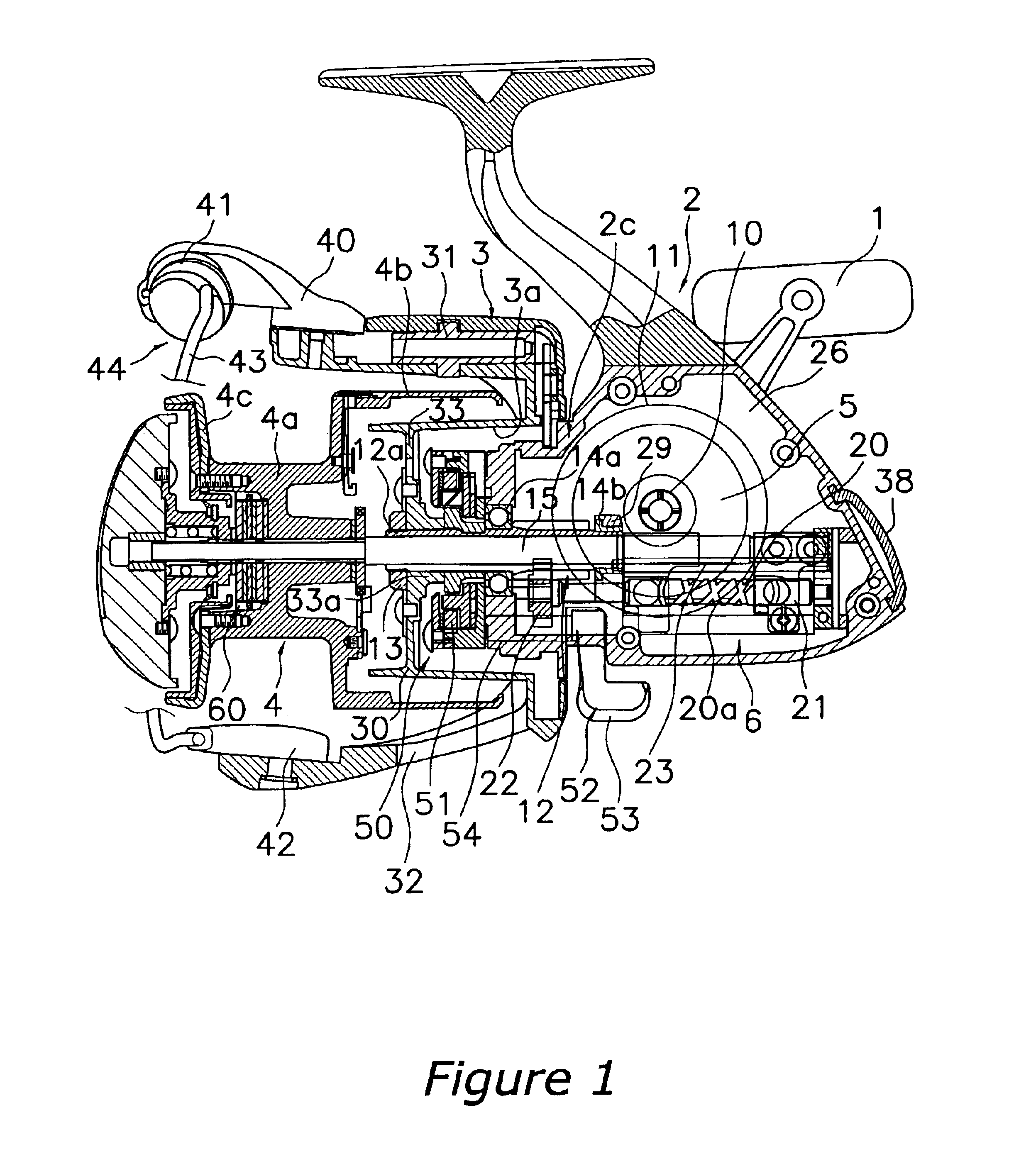
Referring initially to FIG. 1, a spinning reel is illustrated in accordance with a first embodiment of the present invention.

As shown in FIG. 1, a spinning reel in accordance with an embodiment of the present invention is a large spinning reel, which is provided primarily with a reel unit 2 that rotatably supports a handle 1 and is to be mounted to a fishing rod, a rotor 3, a spool 4, a rotor driving mechanism 5 and an oscillation mechanism 6. The rotor 3 is for winding fishing line on the spool 4 and is supported rotatably at the front of the reel unit 2. The spool 4 is for winding fishing line around it...


PUM


Abstract

A worm shaft attachment structure for a spinning reel includes a mechanism attachment portion having a first attachment portion, and a locking member. The rear end of a worm shaft is attached to the first attachment portion, which includes an aperture portion and a bearing mounting portion that is depressed from the aperture portion in a first direction. The bearing mounting portion can come into contact with an outer circumferential surface of the first bearing, which is mounted to the rear end of the worm shaft. The locking member is mounted detachably to the first attachment portion so as to close the aperture portion, and restricts shifting of the first bearing in the first direction by abutting against the outer circumferential surface of the first bearing. This way, the precision with which a worm shaft is attached is ensured, and the restrictions on the design options are reduced.

Description

BACKGROUND OF THE INVENTION1. Field of the InventionThis invention generally relates to worm shaft attachment structures. More specifically, the present invention relates to worm shaft attachment structures, in which a worm shaft is attached rotatably to a reel unit via first and second bearings that are disposed at the two ends of the worm shaft, wherein intersecting helical grooves are formed on an outer circumferential surface of the worm shaft, and the worm shaft is for reciprocating a spool back and forth in cooperation with a rotation of a handle, the spool being for winding line on a spinning reel.2. Background InformationTypical spinning reels include a reel unit, a rotor rotatably supported by the reel unit, and a spool around which fishing line can be wound. The rotor has a pair of arm portions. Between the two arm portions, a bail is provided that can be switched between a line-winding posture and a line-releasing posture. Furthermore, a line roller for guiding fishing li...

Claims


Application Information

Patent Timeline
IPC IPC(8): A01K89/01A01K89/00
CPCA01K89/0114A01K89/01A01K89/015
Inventor CHIN, GOH MIANG
Owner SHIMANO INC
Learn More