Ultra high vacuum ferrofluidic seals and method of manufacture

a high-vacuum, ferrofluidic technology, applied in the field of ferrofluidic seals, can solve the problems of difficult manufacturing, assembly, maintenance of seals, and inability to survive the high-temperature baking procedure commonly used

Inactive Publication Date: 2005-02-22
FEEROTEC USA
View PDF19 Cites 41 Cited by
  • Summary
  • Abstract
  • Description
  • Claims
  • Application Information

AI Technical Summary

Benefits of technology

In accordance with the principles of the invention, a metal seal comprised of two knife-edges and a flat metal washer is formed between a pole piece and the housing at the axial interface between the parts. One knife-edge is machined into the inner face of the integral housing flange and the other knife-edge is machined into the opposing pole piece face. This metal seal effectively seals the pole piece to the housing with a seal suitable for ultra high vacuum applications.

Problems solved by technology

In addition, rubber O-rings, such as O-rings 118 and 120 typically have operational temperature limits less than 200° C., and, therefore, are unable to survive the high temperature baking procedure commonly used in UHV process to complete outgassing of the vacuum chamber.
However, welded joints frequently cause difficulties in manufacturing, assembly, and maintenance of the seals.

Method used


Image

  • Ultra high vacuum ferrofluidic seals and method of manufacture
  • Ultra high vacuum ferrofluidic seals and method of manufacture
  • Ultra high vacuum ferrofluidic seals and method of manufacture

Examples


Embodiment Construction

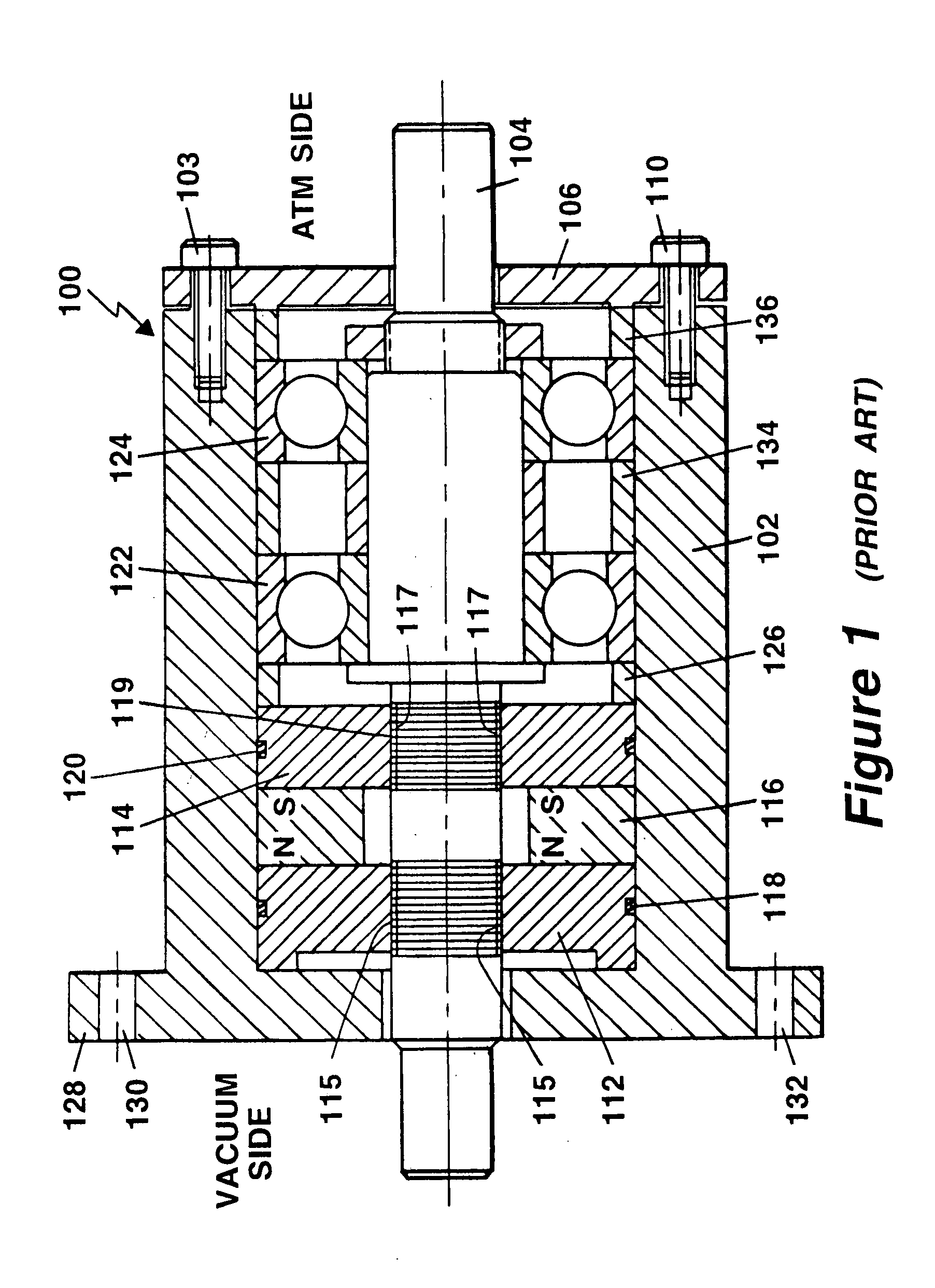
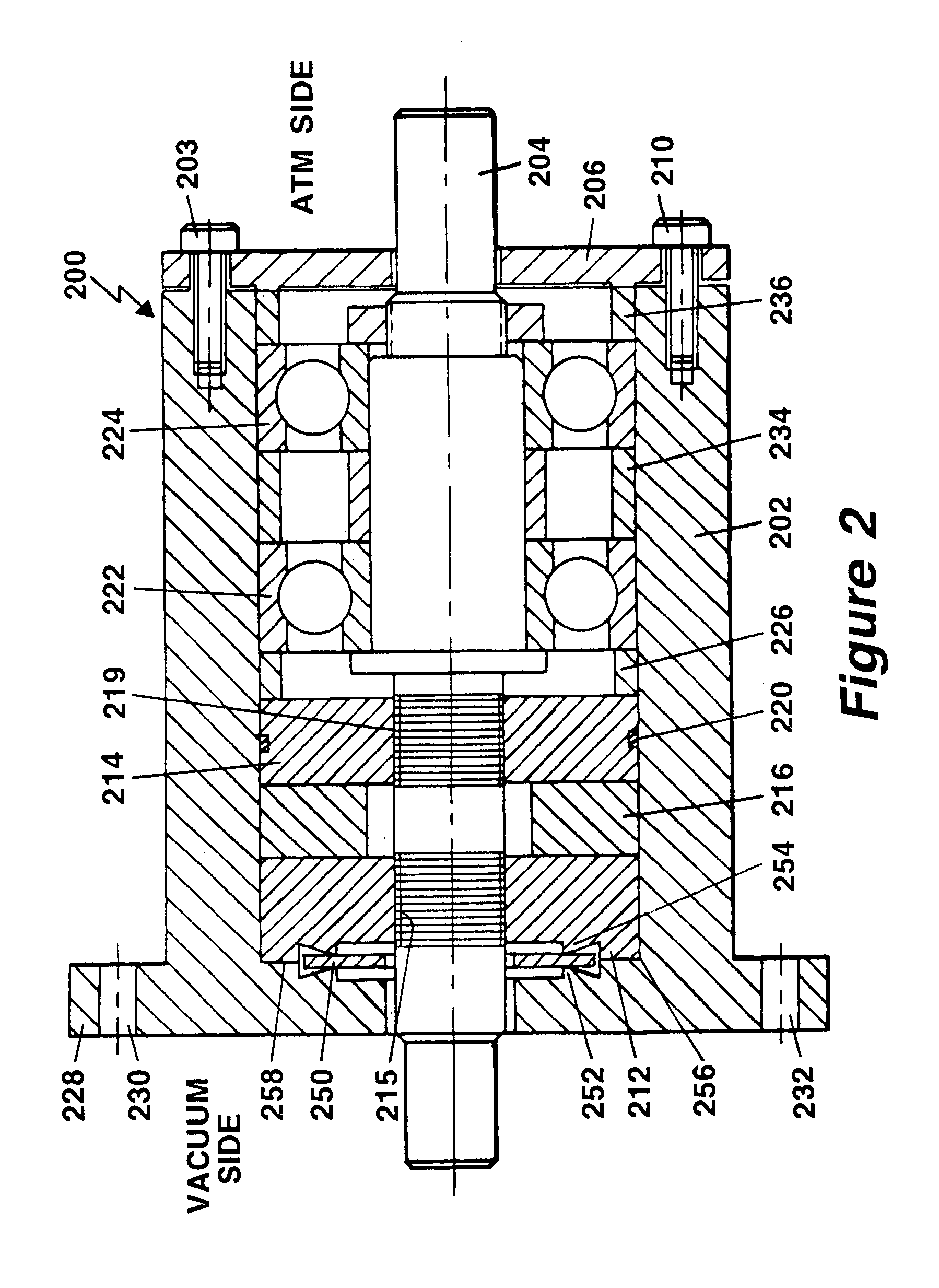
In one embodiment, a metal seal comprised of two knife-edges and a flat metal washer is formed between the outer pole piece 212 and the housing 202 at the axial interface 256 as shown in FIG. 2. In FIG. 2, elements that correspond with similar elements in FIG. 1 have been given corresponding numeral designations. For example, housing 102 in FIG. 1 corresponds to housing 202 in FIG. 2. One knife edge 252 is machined into the inner face 258 of the integral housing flange 228 and the other circular knife edge 254 is machined into the opposing face of the outer pole piece 212. In one embodiment, the knife edges 252 and 254 are circular with the same diameter. The knife edges 252 and 254 could also have other configurations as long as they have a closed circumference. A metal flat washer 250, typically made of copper, is placed in between the two knife-edges 252 and 254. The force generated by tightening the clamping screws of which two 203 and 210 are shown that mount the end cap 206 to...


PUM


Abstract

A ferrofluid seal incorporates a metal seal comprised of two knife-edges and a flat metal washer is formed between a pole piece and the housing at the axial interface between the parts. One knife edge is machined into the inner face of the housing flange and the other knife edge is machined into the opposing pole piece face. This metal seal effectively seals the pole piece to the housing with a seal suitable for ultra high vacuum applications.

Description

FIELD OF THE INVENTION This invention relates to ferrofluidic seals for use in an ultra high vacuum environment. BACKGROUND OF THE INVENTION Ferrofluidic rotary seals have been widely used in vacuum applications over the past 20 years. The basic structure of a conventional ferrofluid seal is illustrated in FIG. 1, which is a partial cross-sectional view of an axially symmetric seal. The seal 100 comprises a non-magnetic housing 102 through which a magnetically permeable rotary shaft passes 104. The housing 102 is closed by a non-magnetic end cap 106 that is fastened to the housing 102 by a plurality of clamping screws of which screws 103 and 110 are shown. A pair of ferrofluid seals is formed of an outer annular pole piece 112 fabricated of magnetically permeable material and an inner annular pole piece 114 also fabricated of magnetically permeable material. Pole pieces 112 and 114 are separated by an axially-polarized toroidal magnet 116. The magnet 116, the poles 112, 114 and the ...

Claims


Application Information

Patent Timeline
Patent Type & Authority Patents(United States)
IPC IPC(8): F16J15/06F16J15/40F16J15/08F16J15/43
CPCF16J15/062F16J15/43F16J15/0881
Inventor LI, ZHIXINSCHREIBER, ANDREWZINSSTAG, JURGEN
Owner FEEROTEC USA
Why Eureka
Try Eureka