Device for acupuncture

a technology for acupuncture and devices, applied in the field of acupuncture devices, can solve the problems of inconvenient use, inability to achieve the desired acupuncture treatment effect, and the problem of conventional devices for acupuncture, and achieve the effect of maximizing the desired synergistic effect and being convenient to us

Inactive Publication Date: 2005-02-22
KIM CHI KYUNG
View PDF9 Cites 17 Cited by
  • Summary
  • Abstract
  • Description
  • Claims
  • Application Information

AI Technical Summary

Benefits of technology

Another object of the present invention is to provide a device for acupuncture, of which the plate-type unit cell is designed to be easily assembled with one or more additional unit cells into a plate-type assembly having a desired area.
A further object of the present invention is to provide a device for acupuncture, which has an integrated radiation member capable of commonly radiating desired far infrared rays, anions and lines of magnetic force at the same time, and which is structurally designed to allow desirably intensive far infrared rays, anions and lines of magnetic force from the integrated radiation member to be concentratively radiated onto a desired specified area of the human body, and thereby to maximize the desired synergistic effect.

Problems solved by technology

However, conventional devices for acupuncture are problematic as follows.
Due to such a flat surface of the body contact portion of the magnetic body 20, the lines of magnetic force, emitted from the magnet 10 and passing through the magnetic body 20, fail to be concentrated onto a desired specified spot on the skin of the human body, may be undesirably dispersed, thus almost failing to accomplish a desired acupuncture treatment effect.
Another problem resides in that their radiation members for emitting far infrared rays, anions and lines of magnetic force are separately manufactured and are separately sold in markets, thus forcing users to separately purchase them while paying excessive money and to use them separately during an acupuncture treatment and thereby being very inconvenient to the users.

Method used


Image

  • Device for acupuncture
  • Device for acupuncture
  • Device for acupuncture

Examples


Embodiment Construction

Hereinafter, preferred embodiment of the present invention will be described in detail with reference to the accompanying drawing.

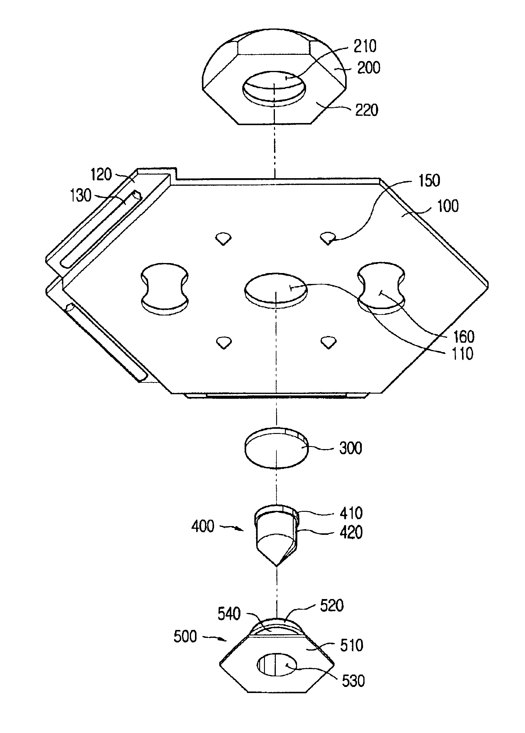
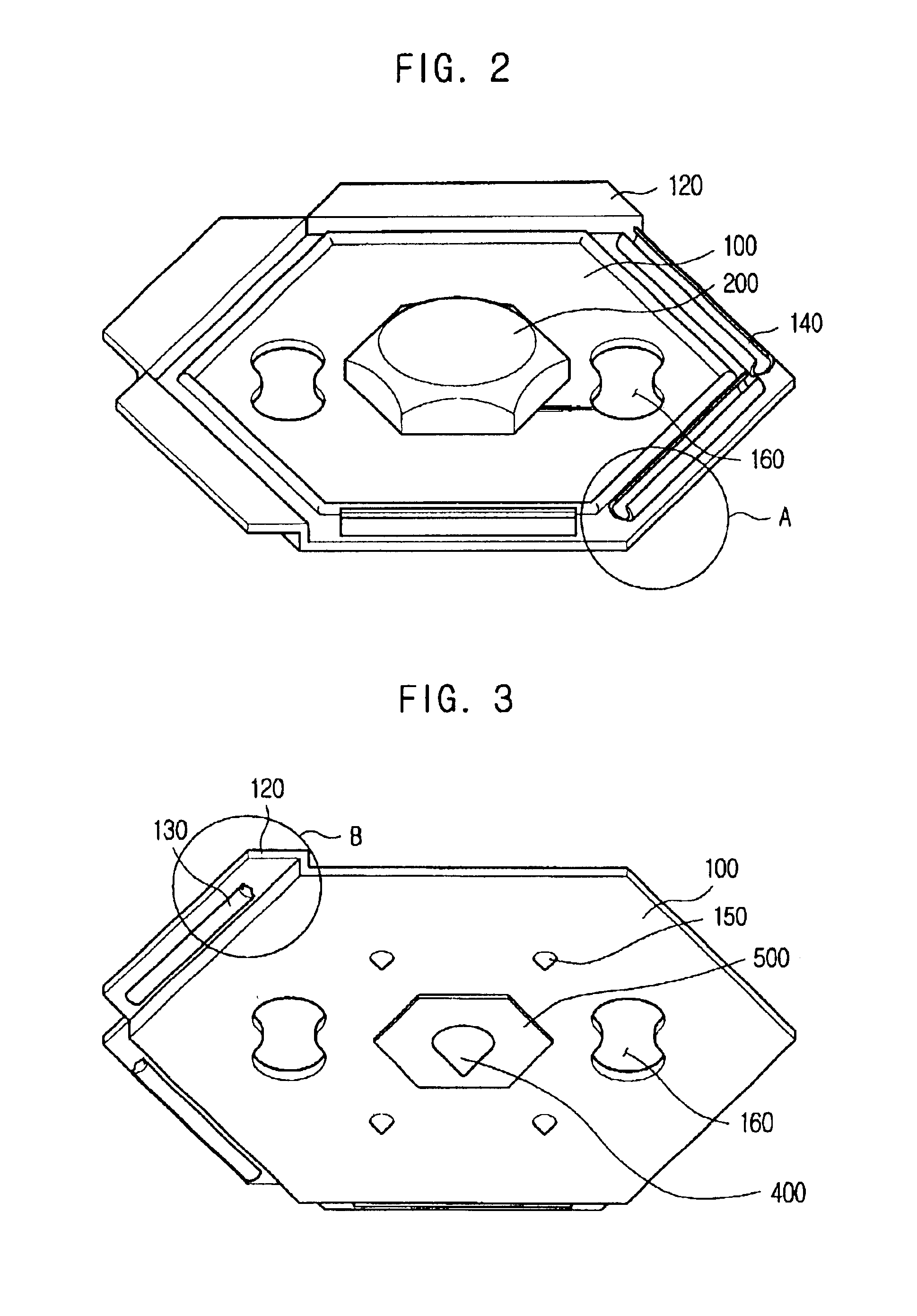
FIGS. 2 to 4 show an acupuncture device formed as a plate-type unit cell in accordance with the primary embodiment of the present invention. As shown in the drawings, the acupuncture device of this invention is formed as a plate-type unit cell for acupuncture. This unit cell is composed of a pressure plate 100, with a cap 200 having a regular hexagonal of the pressure plate 100. Both a magnet 300 and a magnetic body 400 are set within the cap 200 in a way such that the magnet 300 positioned on the interior surface of the top wall of said cap 200, with the magnetic body 400 coming into contact with the lower surface of the magnet 300 at its top surface and extending downwardly to be partially exposed outside the lower surface of the pressure plate 100 at its lower conical tip. A tubular member 500 is firmly fitted in a central opening of the pressure plate...


PUM


Abstract

A device for acupuncture is disclosed. The device has a pressure plate 100 having a polygonal profile. Both a magnet 300 and a magnetic body 400 are set in the pressure plate 100, with the magnetic body 400 being brought into contact with the magnet 300 at its upper end. The magnetic body 400 also extends through the pressure plate 100 so as to project outside the lower surface of the plate 100 at its lower end. The pressure plate 100 is also provided with both a plurality of fitting rods 130 and the same number of channelled fitting tubes 140. When it is desired to assemble two or more pressure plates 100 into an assembly, the fitting rods 130 of one plate 100 are elastically coupled to the channelled fitting tubes 140 of another plate 100. A cap 200 is mounted to the upper surface of the plate 100 and seats both the magnet 300 and the magnetic body 400 therein. A tubular member 500 is fitted into the pressure plate 100 from the lower surface of the plate 100 and is locked to the cap 200 at its upper end. The tubular member 500 has a central bore 530 allowing the magnetic body 400 to axially extend through until the conical tip of the magnetic body 400 projects outside the lower surface of the plate 100. This device is formed as a unit cell, and so two or more devices are easily and orderly coupled to each other into an acupuncture assembly, having desired size and shape, when necessary. The device of this invention may be attached to a desired part of the body using a band or may be coupled to each other into a bed mattress-sized assembly preferably usable as a healthful mattress for beds. This device thus allows a user to save money while purchasing such a device and gives a desired acupuncture treatment effect to the user.

Description

BACKGROUND OF THE INVENTION1. Field of the InventionThe present invention relates, in general, to a device for acupuncture and, more particularly, to a structural improvement in such an acupuncture device to directly apply the healthful far infrared rays, anions and lines of magnetic force onto the human body and to allow a user to easily and simply fabricate an acupuncture assembly, having desired shape and size, by appropriately assembling a plurality of acupuncture devices individually formed as a unit cell, having predetermined shape and size, into a desired assembly.2. Description of the Related ArtAs well known to those skilled in the art, a radiation of far infrared rays, anions and lines of magnetic force onto a specified area on the human body is very healthful to the human body, and so several types of devices for acupuncture designed to radiate such far infrared rays, anions and lines of magnetic force onto a desired specified area on the human body have been proposed and...

Claims


Application Information

Patent Timeline
Patent Type & Authority Patents(United States)
IPC IPC(8): A61H39/04A61N5/06A61N2/06A61N2/00A61H39/00A61N1/00A61N2/08
CPCA61H39/04A61N5/0619A61N2/06A61H2039/005A61H2201/10A61N2005/0659A61N2005/0645
Inventor KIM, CHI-KYUNG
Owner KIM CHI KYUNG
Why Eureka
Try Eureka