Method for determining the rotational position of the drive shaft of a direct current motor

Inactive Publication Date: 2005-02-22
LEOPOLD KOSTAL GMBH & CO KG
View PDF8 Cites 27 Cited by
  • Summary
  • Abstract
  • Description
  • Claims
  • Application Information

AI Technical Summary

Benefits of technology

An estimate of the current ripple component in the motor startup and slowdown phases is sufficient for the desired position determination to be sufficiently accurate. Moreover, using such an estimate offer

Problems solved by technology

If the counting of the current ripples to determine the position of the window glass is incorrect, it can happen that the pinching protection is turned off too early or too late.
However, such a process is subject to inaccuracies in determining the exact position due to the DC motor starting when power is supplied to it and slowing down when it is turned off.
These inaccuracies result fro

Method used


Image

  • Method for determining the rotational position of the drive shaft of a direct current motor
  • Method for determining the rotational position of the drive shaft of a direct current motor

Examples


Embodiment Construction

)

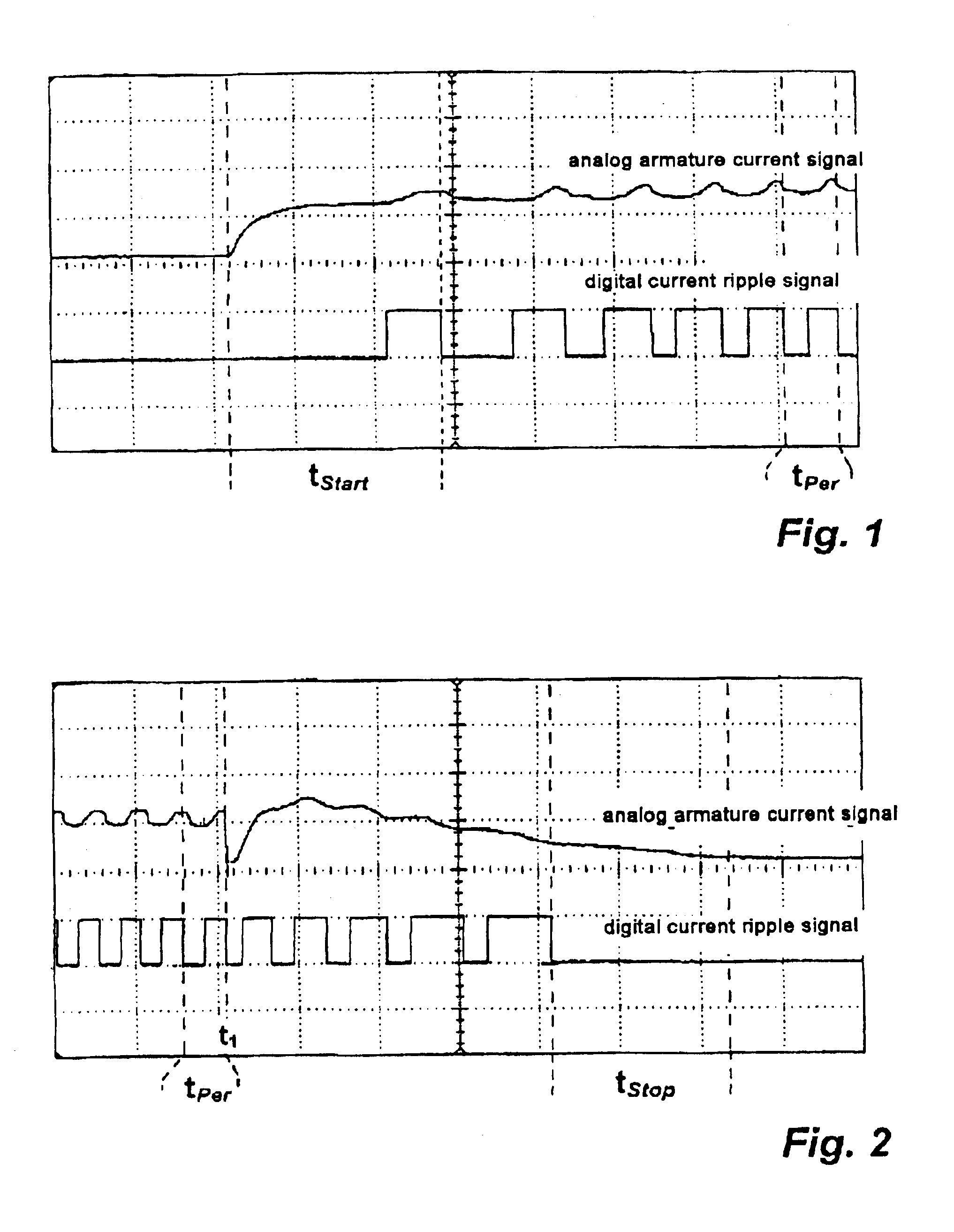
Referring now to FIG. 1, a diagram illustrating the filtered analog armature current signal and, below it, the digital current ripple signal derived from the armature current signal is shown. FIG. 1 also marks the phase during motor startup tStart for which the current ripple component should be determined. It is also possible to identify the period tPer which is used as a reference current ripple in order to be able to make the desired determination of the current ripple component.

It is possible to determine the size of the current ripple component during the first time interval tStart in the following way, for example:

Current ripple component (motor start-up phase)=(tStart·k) / tPer

where k is the motor characteristic constant and tPer is the period of the reference current ripple.

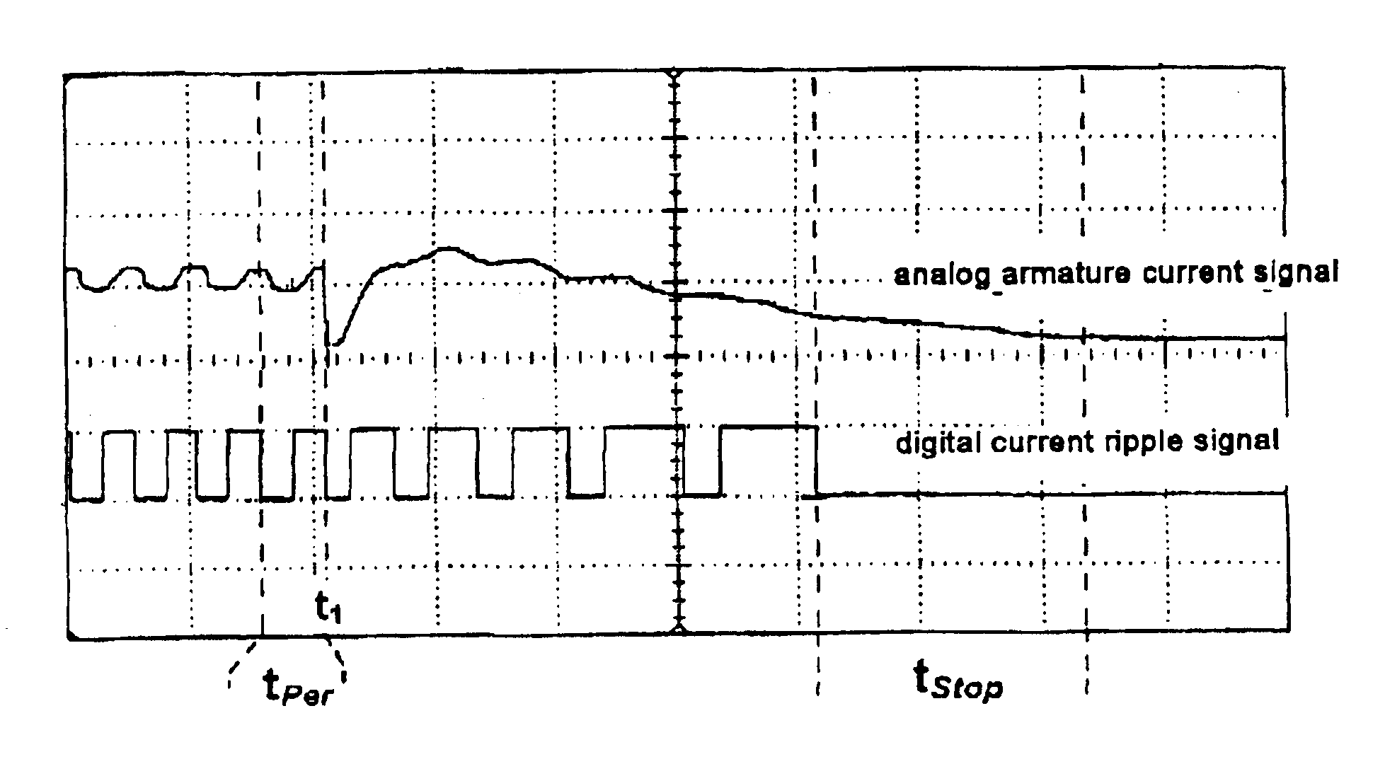
Referring now to FIG. 2, a corresponding diagram illustrating the filtered analog armature current signal and the current ripple determined from it when the motor stops is shown. At time t1 the DC motor is...


PUM


Abstract

A method for determining the position of an element driven along a travel segment by a shaft of a motor includes counting current ripples detected in an armature current signal of the motor as the motor shaft rotates to drive the element. A first time interval between when the motor is turned on with power being supplied to the motor and when the first current ripple is detected is determined. A second time interval between when the last current ripple is detected after the motor has been turned off with the power supplied to the motor being interrupted and when the motor shaft stops rotating is determined. First and second current ripple components corresponding to the first and time intervals, respectively, are estimated. The position of the element along the travel segment is determined based on the counted current ripples and the estimated first and second current ripple components.

Description

BACKGROUND OF THE INVENTION1. Field of the InventionThe present invention relates to a method for determining the rotational position of the drive shaft of a direct current (DC) motor by evaluating the current ripple contained in the armature current signal.2. Background ArtThe armature current signal of a direct current (DC) motor includes a so-called direct component and a ripple component superimposed on the direct component. The ripple component arises when the DC motor is operated as a consequence of the interaction of the magnetic field, the armature winding, and the commutator of the DC motor. This expresses itself in a short-term change in the induced voltage, which produces the ripple content of the armature current signal. The current peaks contained in the armature current signal (referred to below as “current ripple”) occur when the armature rotates, and have a frequency corresponding to the number of collector bars.For example, if the armature has ten collector bars, th...

Claims


Application Information

Patent Timeline
IPC IPC(8): G01P3/42G01P3/48H02P7/18H02P7/29E05F15/16H02P7/06H02P7/00
CPCG01P3/48H02P7/2913H02P7/0094E05Y2900/55E05F15/695
Inventor OTTE, STEFAN
Owner LEOPOLD KOSTAL GMBH & CO KG
Why Eureka
Try Eureka