Electro-optical apparatus and projection-type display apparatus

a technology of optical apparatus and projection-type display apparatus, which is applied in the field of optical apparatus, can solve problems such as the potential fluctuation of the opposite electrod

Inactive Publication Date: 2005-02-22
138 EAST LCD ADVANCEMENTS LTD
View PDF15 Cites 39 Cited by
  • Summary
  • Abstract
  • Description
  • Claims
  • Application Information

AI Technical Summary

Benefits of technology

The present invention has been made in consideration of the foregoing problems. It is an object of the present invention to provide an electro-optical apparatus in which a parasitic capacitor generated between a wire and others disposed on one substrate and an opposite electrode disposed on the other substrate opposite the one substrate is reduced by a relatively simple structure to reduce a potential fluctuation of the opposite electrode due to the parasitic capacitor and thereby, a high-quality image display with a reduced ghost is allowed, and a manufacturing method therefor.
According to this form, opposite substrates can be easily cut off along the cutting lines formed on the mother board while the dicing blade is being rotated.

Problems solved by technology

When wires on the TFT array substrate, such as the image signal lines and lead wires extended from the image signal lines, and the opposite electrode on the opposite substrate are disposed oppositely as described above, however, parasitic capacitors generated therebetween cause a potential fluctuation of the opposite electrode due to potential fluctuations of image signals.
Especially in a case in which data is shown on a personal-computer screen, a block-shaped ghost is visually more conspicuous, although it may be inconspicuous when a motion image is displayed.

Method used


Image

  • Electro-optical apparatus and projection-type display apparatus
  • Electro-optical apparatus and projection-type display apparatus
  • Electro-optical apparatus and projection-type display apparatus

Examples


Embodiment Construction

Embodiments of the present invention will be described below by referring to the drawings. In the following embodiments, an electro-optical apparatus of the present invention is applied to a liquid-crystal apparatus.

The entire structure of an electro-optical apparatus according to an embodiment of the present invention will be described first by referring to FIG. 1 and FIG. 2. A driving-circuit-built-in-type liquid-crystal apparatus using a TFT active matrix driving method is taken as an example of an electro-optical apparatus.

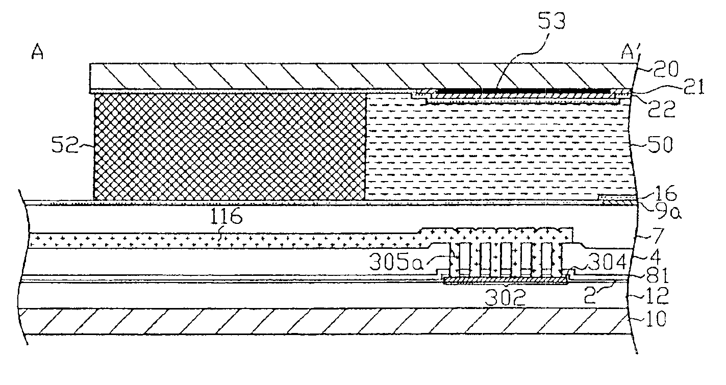
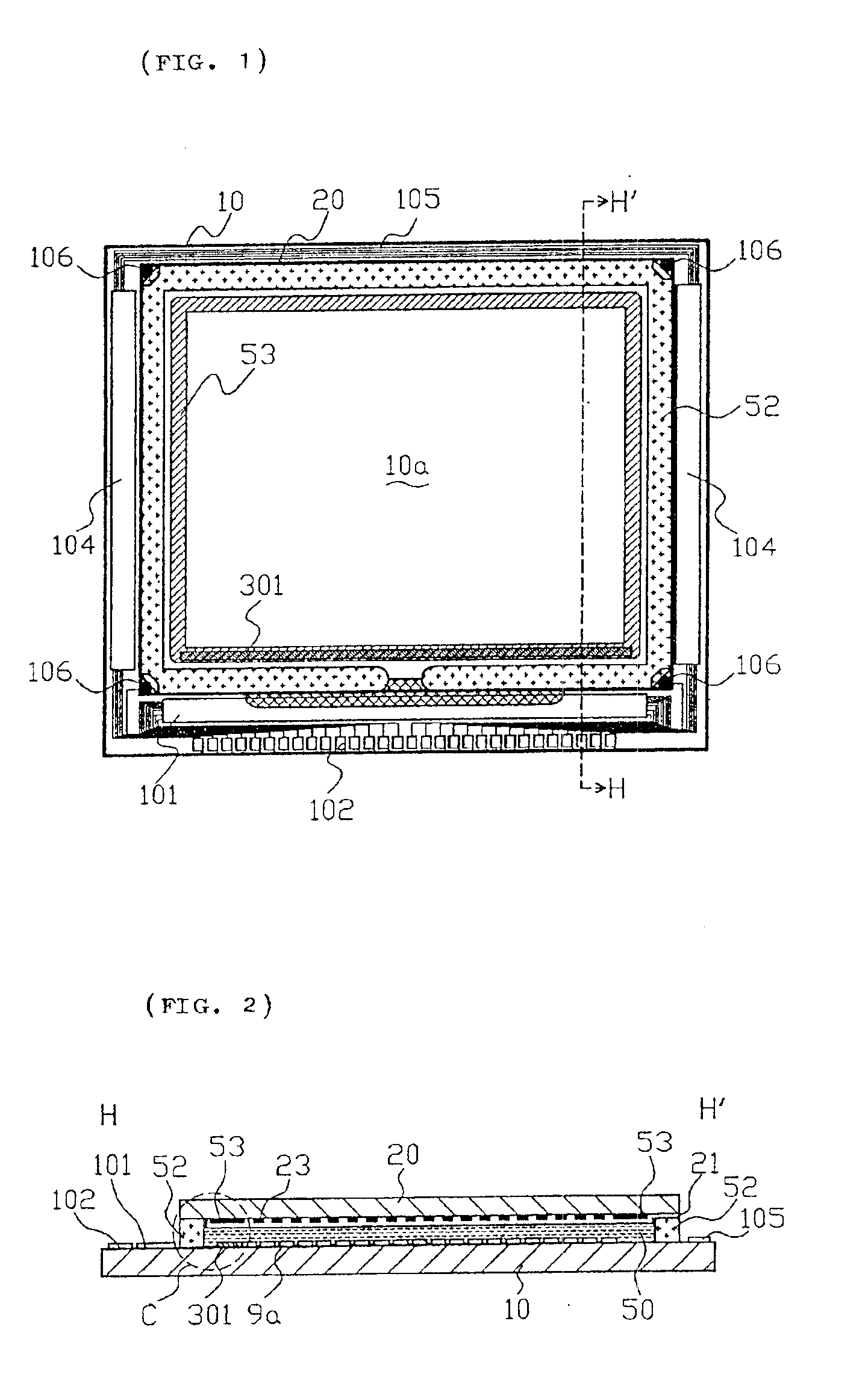
FIG. 1 is a plan of a TFT array substrate and each component formed thereon, viewed from an opposite-substrate side. FIG. 2 is a sectional view taken along H-H′ shown in FIG. 1.

In FIG. 1 and FIG. 2, a TFT array substrate 10 and an opposite substrate 20 are disposed oppositely in an electro-optical apparatus according to the present embodiment. A liquid-crystal layer 50 is sealed between the TFT array substrate 10 and the opposite substrate 20. The TFT array su...


PUM

PropertyMeasurementUnit
lengthaaaaaaaaaa
thicknessaaaaaaaaaa
areaaaaaaaaaaa

Abstract

In an electro-optical apparatus, such as a liquid-crystal apparatus, a TFT array substrate is provided with pixel electrodes and TFTs connected thereto. In addition, a peripheral area (including a frame area and a sealing area) is provided with peripheral circuits that drive the pixel electrodes, such as data-line driving circuits and a sampling circuit, and wires that send image signals. On an opposite substrate, an opposite electrode is formed so as to avoid areas opposite the wires. Therefore, with a relatively simple structure, parasitic capacitors generated between the wires on one substrate and the opposite electrode on the other substrate are reduced, and high-quality image display having a reduced ghost is achieved.

Description

BACKGROUND OF THE INVENTION1. Field of the InventionThe present invention belongs to the technical fields of electro-optical apparatuses, such as a liquid-crystal apparatus, in which an electro-optic material is sandwiched by a pair of substrates and a pair of electrodes disposed at sides facing the electro-optic material in the pair of substrates is provided, and of manufacturing methods therefore.2. Description of the Related ArtThis type of electro-optical apparatuses are generally provided with a TFT array substrate having pixel electrodes, thin-film transistors (hereinafter called TFTs (Thin Film Transistors), if necessary) for applying switching control to the pixel electrodes, and wires, such as data lines connected to the thin-film transistors, for sending image signals and scanning lines for sending scanning signals. In addition, an opposite substrate having a color filter, a light-shielding film, and an opposite electrode disposed on the whole surface and disposed opposite...

Claims


Application Information

Patent Timeline
Patent Type & Authority Patents(United States)
IPC IPC(8): G02F1/13G02F1/1362G02F1/1341G02F1/1343G02F1/1345G03B21/00G09F9/00G09F9/30G09F9/35
CPCG02F1/136286G02F1/13454
Inventor MURADE, MASAOUCHIDA, MASAHIDE
Owner 138 EAST LCD ADVANCEMENTS LTD
Why Eureka
Try Eureka