Optical observation device and method for observing articles at elevated temperatures

a technology of optical observation and objects, applied in lighting and heating apparatus, television systems, instruments, etc., can solve the problems of limiting the ability of workers to physically interact with other objects, physical injury to workers, and limiting their mobility

Inactive Publication Date: 2005-02-22
OG TECH INC
View PDF40 Cites 38 Cited by
  • Summary
  • Abstract
  • Description
  • Claims
  • Application Information

AI Technical Summary

Benefits of technology

[0015]In still another aspect, the present invention is implemented in a hand-held device.

Problems solved by technology

Direct exposure to infrared (IR) radiation, however, could cause physical injury to the workers.
However, the use of light shields often restricts the workers' mobility.
For example, wearing a light shield may restrict their ability to physically interact with other objects that are not glowing, such as tools, controls and the like.
Additionally, the “illumination” is self-emitted and thus often carries unwanted information.
Images collected via this passive method are generally not suitable for automatic machine vision applications.
Several problems, however, are associated with the active approach.
First, few light sources exist that can overpower the radiation emitted by an object at 1350° C. Second, the self-emitted radiation still represents a problem: it degrades the signal quality of the reflected radiation.
Third, these external light sources may be undesirable in the work environment because they are so intense.
However, the use of lasers poses substantial problems.
While lasers deliver high power density, the areas illuminated by the laser beams are small.
Moreover, these high power lasers are expensive, bulky, and pose various risks.
The use of infrared (IR) sensors or cameras in a passive method vision system are also of limited value due to several factors.
First, IR sensors / cameras provide significantly less pixel resolution than their CCD counterparts.
Second, IR radiation cannot be focused as well as visible light due to its wavelength.
Third, using IR sensors / cameras does not solve the problems associated with illumination or the Cavity Radiator Effect previously described.
There have been attempts to use a combination of passive and active methods, but this approach does not resolve the issues posed by the Cavity Radiator Effect and self-emitted radiation.
This approach is ill-conceived because a hot object can radiate with both IR and visible light radiation.
In addition, if the self-emitted radiation is not removed from the collected signal, the noise caused by the self-emitted radiation impairs the system's ability to gather detailed and accurate information about the hot object.
The prior art lacks an effective means of removing the self-emitted radiation from the collected signal of a hot object.
Finally, it is also believed that none of the devices enabled by the prior art is portable.
This fact has limited the utility of such devices for certain applications.
The external light sources used in prior art devices are too powerful and / or heavy to be low-risk and portable.
In summary, the prior art approaches have been of limited value.

Method used


Image

  • Optical observation device and method for observing articles at elevated temperatures
  • Optical observation device and method for observing articles at elevated temperatures
  • Optical observation device and method for observing articles at elevated temperatures

Examples


example

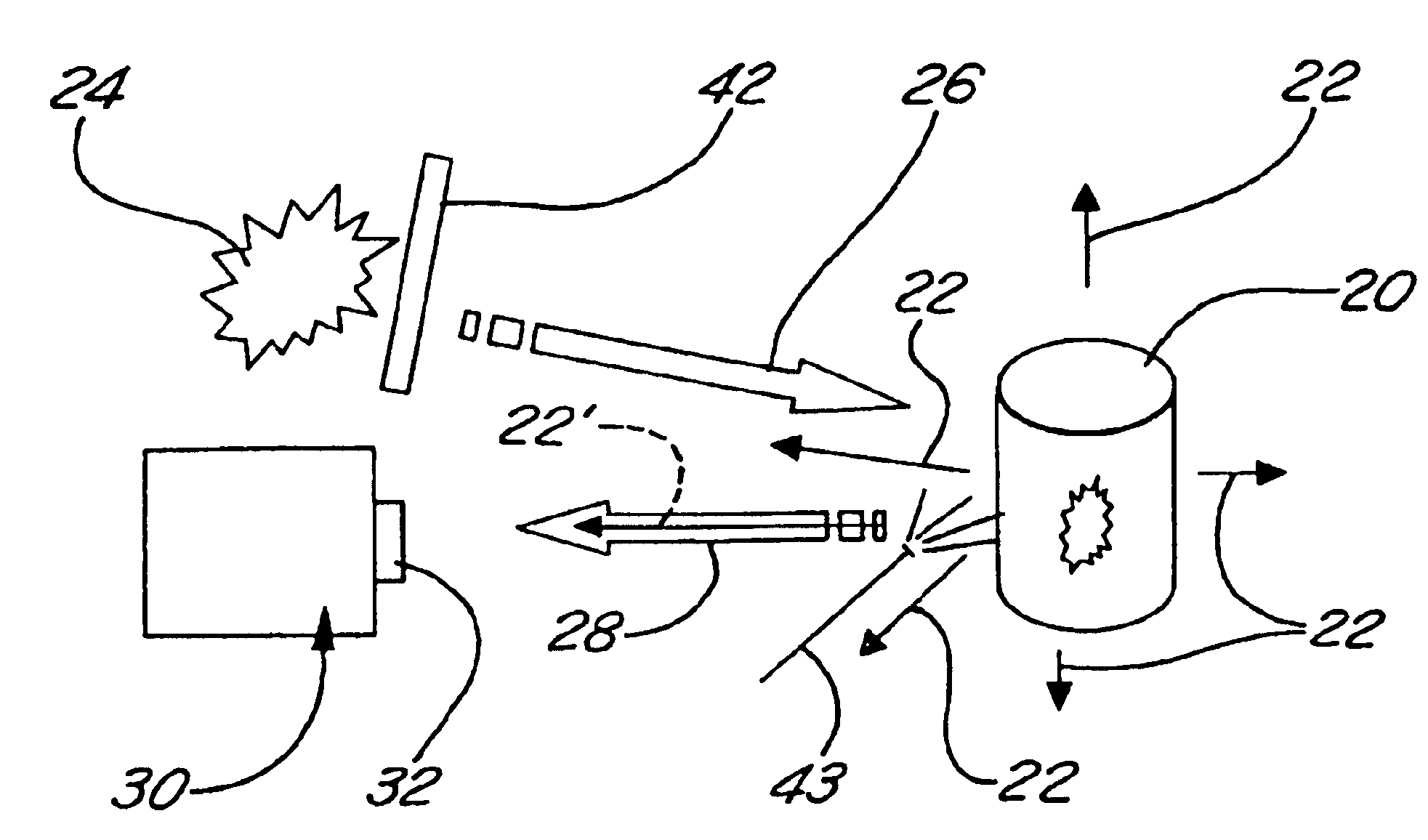
[0078]An example of the present invention in one embodiment is as follows:

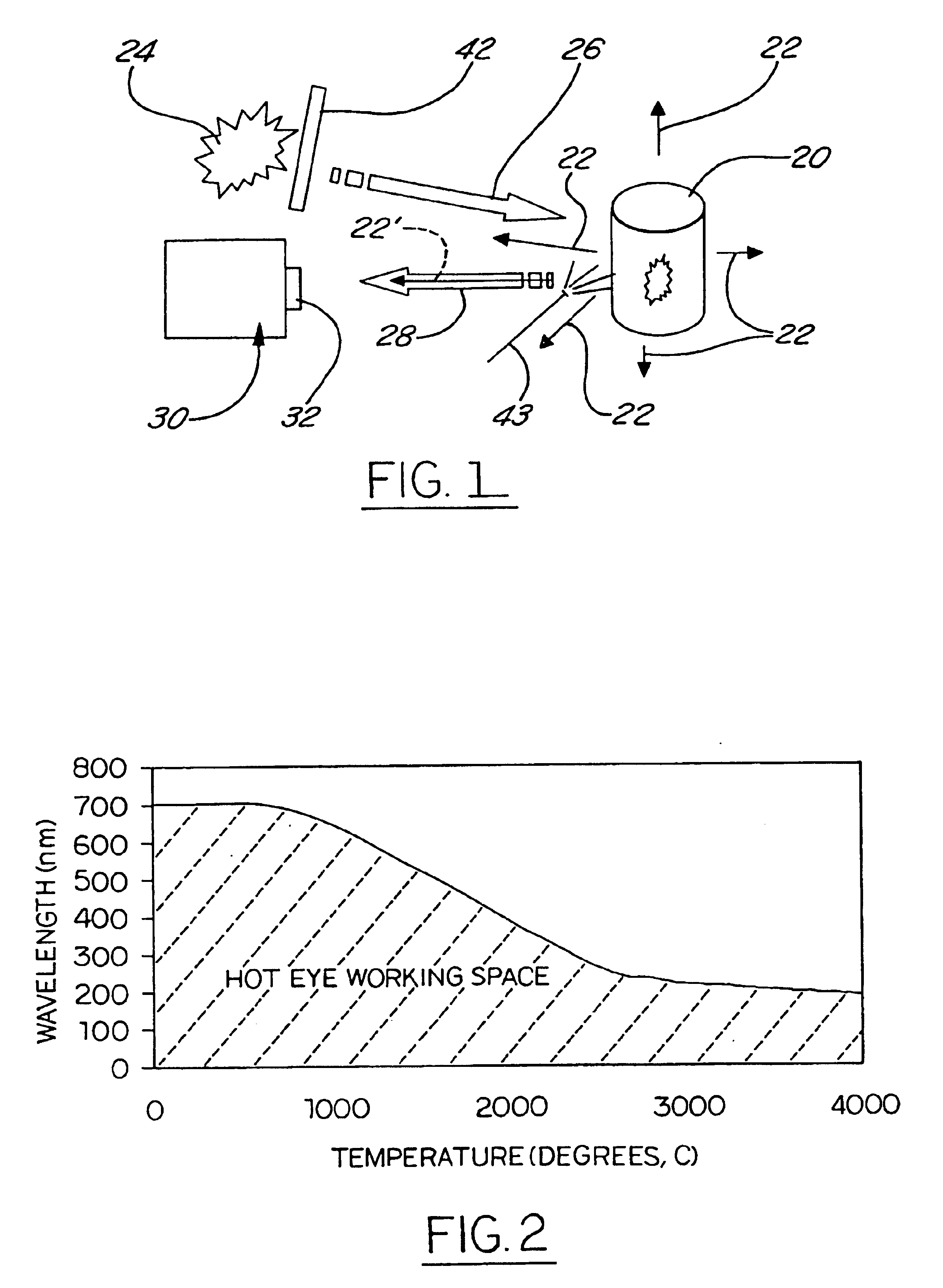
[0079]1. The external illumination source is a halite lamp. The halite radiation consists of three principal wavelengths, 435 nm, 550 nm, and 575 nm. The radiation at 435 nm is the most useful wavelength in this design because it is the farthest one away from the self-emitted radiation of a hot object. The hot object must be at a temperature of 1800° C. or hotter for its self-emitted radiation to cover 435 nm, assuming the hot object is close to a black body.

[0080]2. The external radiation is projected onto the hot object and interacts with the surface of the hot object. The reflected radiation from the metal halite lamp (with all three distinct wavelengths), the self-emitted radiation from the hot object, and any other radiation present are all blended together.

[0081]3. The blended radiation is then passed through an interference filter, which has a working wavelength at 435 nm. That is, only the radiation at...


PUM

PropertyMeasurementUnit
temperatureaaaaaaaaaa
temperaturesaaaaaaaaaa

Abstract

An optical system for viewing hot objects is disclosed. The system projects electromagnetic radiation to the part surface and detects the reflected portion. Based on wavelength and/or modulation of the applied illumination, the surface characteristics of the part can be observed without interference from self-emitted radiation.

Description

[0002]This application claims the benefit of U.S. Provisional Application Ser. No. 60 / 151,565 filed Aug. 31, 1999.FIELD OF THE INVENTION[0003]The present invention relates generally to methods and devices for optically observing objects at high temperatures, including objects having significant self-emitted radiation.BACKGROUND OF THE INVENTION[0004]In a number of industries, workers still visually inspect hot, glowing objects with their unprotected eyes. Direct exposure to infrared (IR) radiation, however, could cause physical injury to the workers. Accordingly, in some instances, light shields are worn which attenuate the radiation, thus providing some protection against IR exposure. However, the use of light shields often restricts the workers' mobility. For example, wearing a light shield may restrict their ability to physically interact with other objects that are not glowing, such as tools, controls and the like.[0005]Conventional optical inspection devices have also been used...

Claims


Application Information

Patent Timeline
Patent Type & Authority Patents(United States)
IPC IPC(8): G01N21/55G01J1/42H04N5/225H04N7/18
CPCG01N21/55G02B27/00
Inventor CHANG, TZYY-SHUH
Owner OG TECH INC
Why Eureka
Try Eureka