Geolocation system with controllable tags enabled by wireless communications to the tags

a wireless communication and geolocation technology, applied in the field of radiotagged object location and tracking system, can solve the problems of not being able to detect (fcc-compliant) communication signals sourced from a relatively remote location, prohibitively expensive addition to the tag's receiver circuitry, and not being able to effectively change the effect of dri

Inactive Publication Date: 2005-02-22
ZEBRA TECH CORP
View PDF12 Cites 36 Cited by
  • Summary
  • Abstract
  • Description
  • Claims
  • Application Information

AI Technical Summary

Benefits of technology

This, coupled with the fact that the system processor knows the travel time from any selected transmission site of a return message back to the known location of the tag, enables the system processor to effectively immediately initiate the transmission of a return spread spectrum burst from a selected auxiliary transmitter site at the exact instant that will ensure that the return burst will arrive at the tag within a very short window after the tag burst so that is effectively be in time alignment with the tag's internal clock.
The modification of the tag's transceiver circuitry involves a relatively minor addition of a delay strobe and a relatively simple spread spectrum demodulator, that relies upon the expectancy that a return burst from an auxiliary transmitter will arrive at the tag within a very short window of time after the tag ‘blink’, during which the tag's internal crystal oscillator is not expected to effectively change (drift).

Problems solved by technology

Now, although the tag radios employed in the geolocation system described in the '287 and '046 patents contain circuitry capable of detecting a low energy query signal from a relatively close, low powered interrogator unit, they are not configured to detect (FCC-compliant) communication signals sourced from a relatively remote location, such as, but not limited to, any of the tag emission readers distributed within the infrastructure of the geolocation system.
This, in turn, implies the need for what is typically a substantially complex and prohibitively expensive addition to the tag's receiver circuitry, since spread spectrum receivers must be synchronized to the incoming signal to a very high degree of accuracy.

Method used


Image

  • Geolocation system with controllable tags enabled by wireless communications to the tags
  • Geolocation system with controllable tags enabled by wireless communications to the tags
  • Geolocation system with controllable tags enabled by wireless communications to the tags

Examples


Embodiment Construction

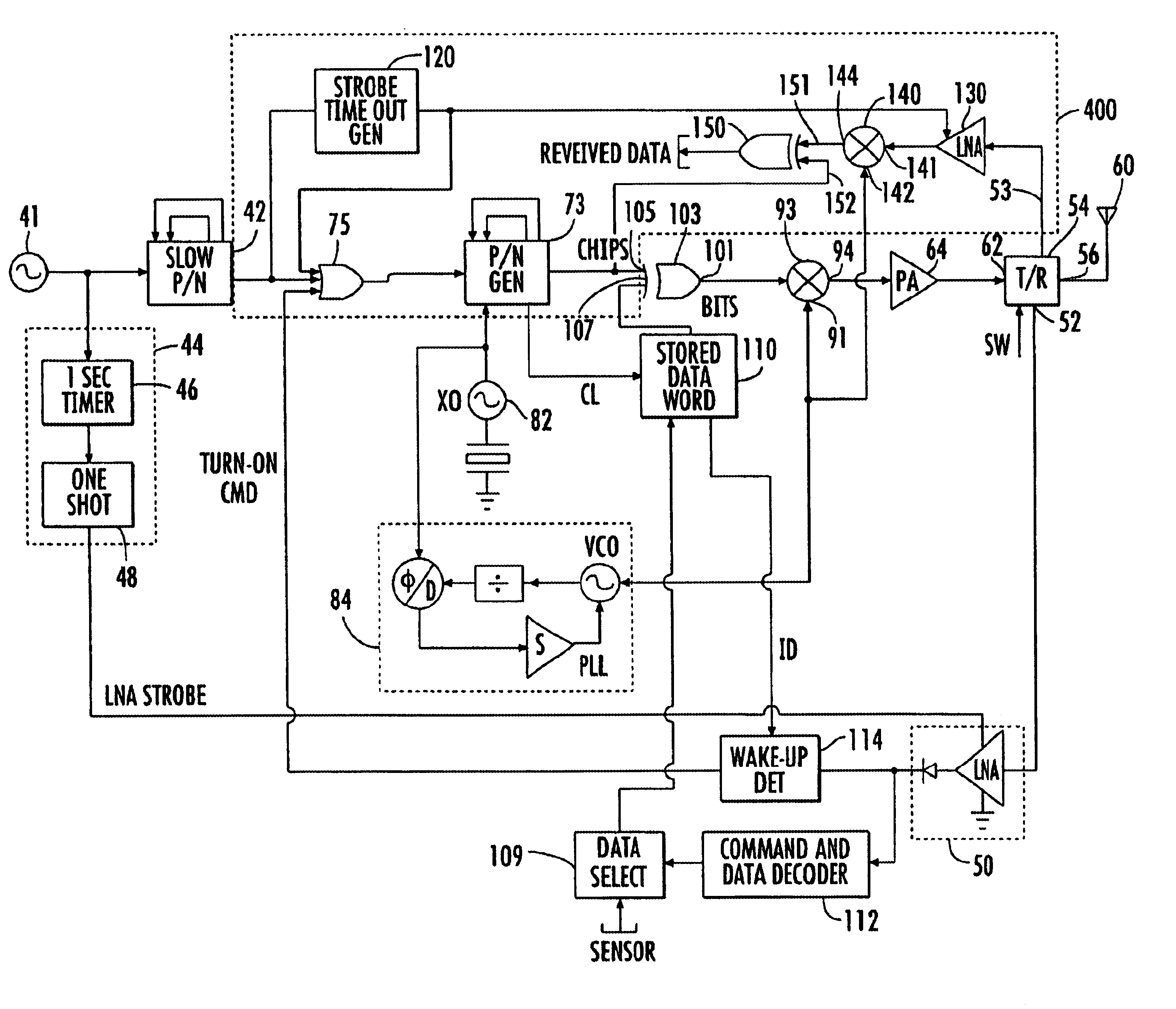
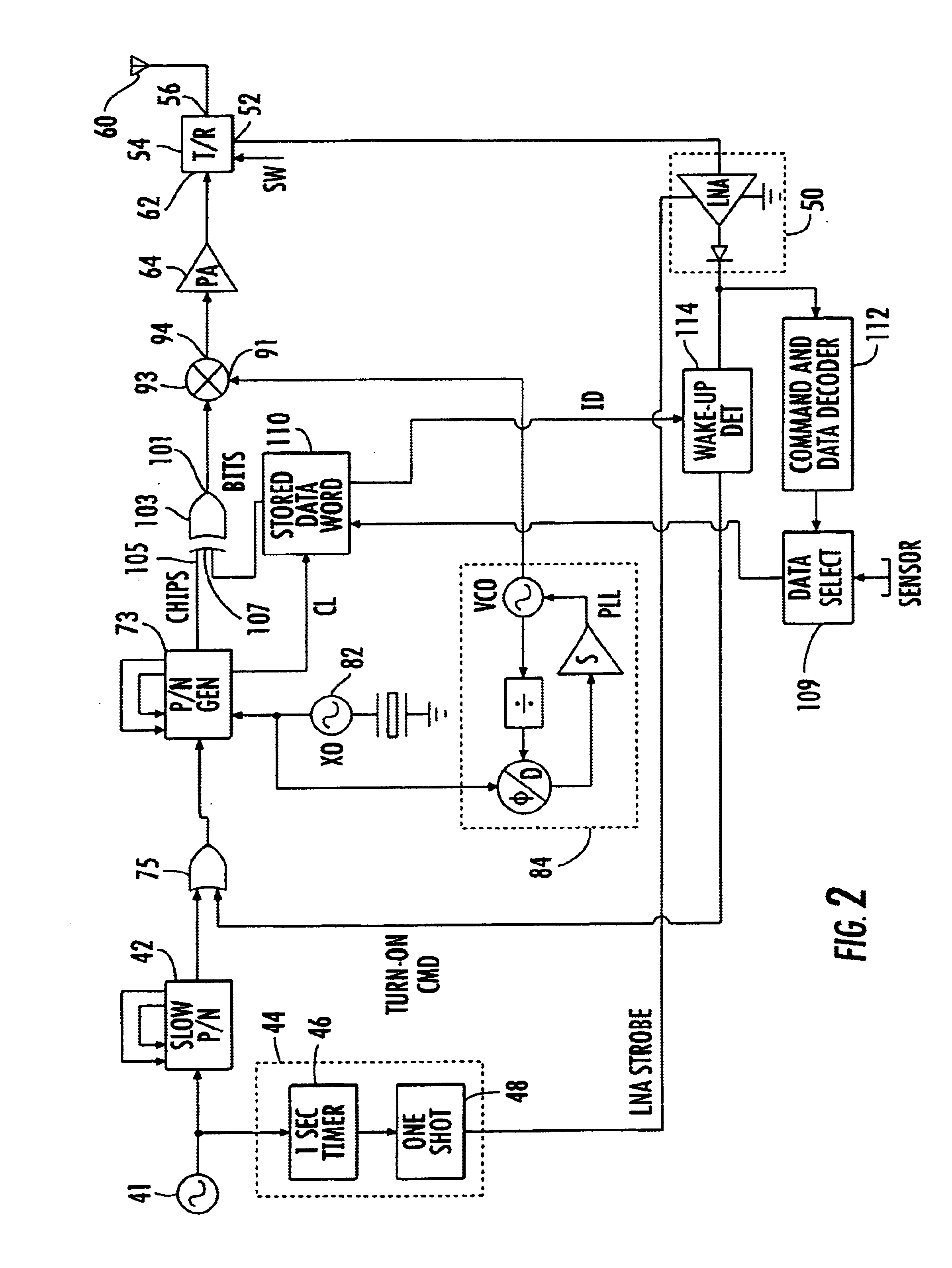
Before detailing the ‘tag clock-synchronized’ return burst transmission scheme of the present invention, it should be observed that the invention is primarily directed to an augmentation to a geolocation system of the type disclosed in the above-referenced Belcher et al '287 and '046 Patents. A first aspect of this augmentation is directed to a modification of the geolocation system's infrastructure that involves the placement in and or around the monitored environment of one or more auxiliary spread spectrum transmitters, whose geo-coordinates are very precisely known (such as, but not limited to the locations of the tag readers). Advantageously, as a complexity and cost reduction measure, the circuitry of these auxiliary transmitters may employ effectively the same transmission architecture as those of the radio tags employed in the above-referenced Belcher et al patents and described previously with reference to FIG. 2.

Operation of a selected auxiliary transmitter is controlled b...


PUM


Abstract

An auxiliary wireless communication mechanism is incorporated into a system that geolocates tagged objects within a monitored environment, using random, repetitive spread spectrum emissions from the tags. The emissions are detected at tag emission readers, and processed by an object location processor to geolocate the tagged objects. The auxiliary wireless communication mechanism transmits a return spread spectrum signal containing information intended for a tag immediately in response to the object location processor geolocating the tag. This immediately returned spread spectrum transmission allows a reduced complexity spread spectrum receiver within the tag to despread the return signal without having to determine the timing of the clock signal used to produce it.

Description

FIELD OF THE INVENTIONThe present invention relates in general to a radio-tagged object location and tracking system of the type described in the U.S. Patents to Belcher et al, U.S. Pat. Nos. 5,920,287 and 5,995,046, (hereinafter referred to as the '287 and '046 patents, respectively), assigned to the assignee of the present application and the disclosures of which are incorporated herein. The system described in the '287 and '046 patents employs a plurality of tag transmission readers geographically distributed within and / or around a tag monitoring area. The readers are coupled to an object location processor, which executes time-of-arrival differentiation of first-to-arrive spread spectrum transmissions from tags as detected by the readers. The present invention is particularly directed to a scheme for automatically conducting a return spread spectrum transmission to a radio-tagged object from a selected transmitter site within the tag monitoring area.BACKGROUND OF THE INVENTIONTh...

Claims


Application Information

Patent Timeline
Patent Type & Authority Patents(United States)
IPC IPC(8): G01S13/00G01S13/87G01S13/82G01S5/06G06K17/00H04B1/69G01S5/02
CPCG01S5/06G01S13/82H04B1/69G06K17/00G01S13/878G01S5/02G06K2017/0045
Inventor BELCHER, DONALD K.
Owner ZEBRA TECH CORP
Why Eureka
Try Eureka