
Bi-directional test system for network analysis

Inactive Publication Date: 2005-02-22
AGILENT TECH INC
View PDF9 Cites 17 Cited by
  • Summary
  • Abstract
  • Description
  • Claims
  • Application Information

AI Technical Summary

Benefits of technology

It is a further object of the present invention to provide a testing system that provides the technician with information about the source of the pro

Problems solved by technology

However, in most systems, the low bandwidth path from the subscriber's premises to the cable headend has not been tested.
Communications from the subscriber's premises to the cable headend are more problematical.
The communications in each direction are isolated from one another; hence, there is no assurance that the path from the subscriber to the cable headend is operational even when it is known that the path from cable headend to the subscriber is functioning properly.
A failure in one of these components can lead to a failure in the communication path from the subscriber to the cable headend while leaving television reception at the subscriber in tact.
Hence, a noise source at one subscriber's location can interfere with communications from all subscriber's on the network.
These problems make it difficult to debug a new communication path from the subscriber to the cable headend.
If the subscriber component does not receive a response to a message sent by it to the cable headend, the technician has no way of determining if the lack of response is due to noise in the path from the subscriber location to the cable headend, a break in that path, someone has turned the cable headend component off, etc.

Method used


Image

  • Bi-directional test system for network analysis
  • Bi-directional test system for network analysis

Examples


Embodiment Construction

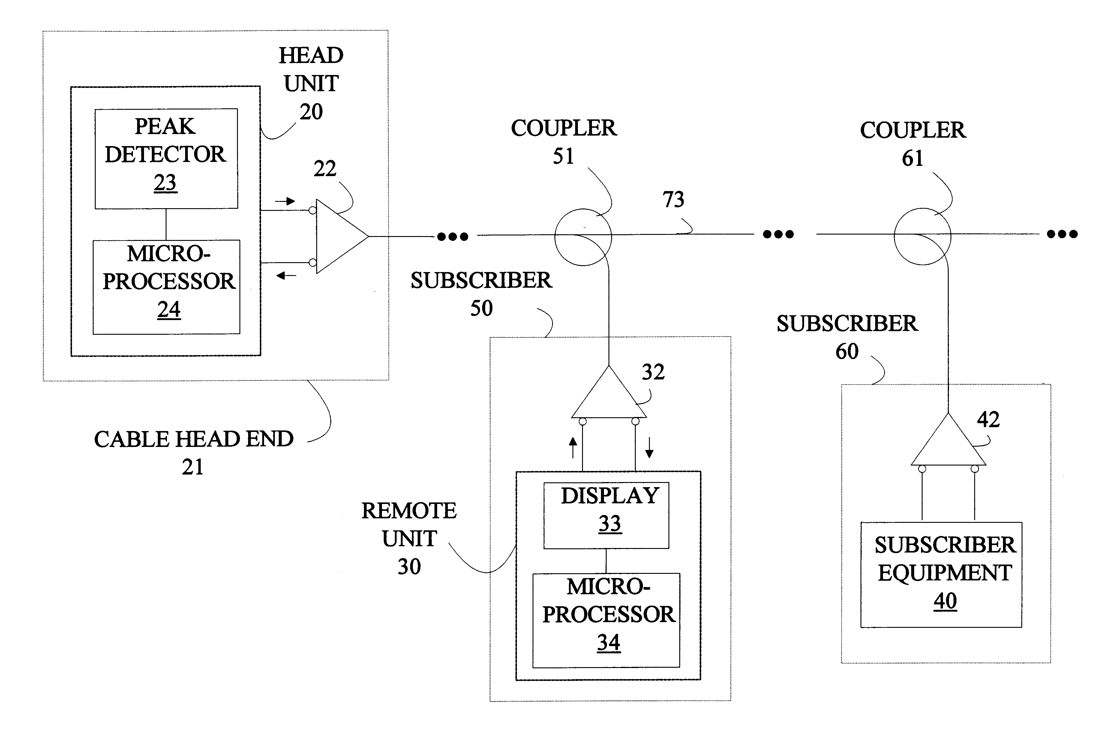
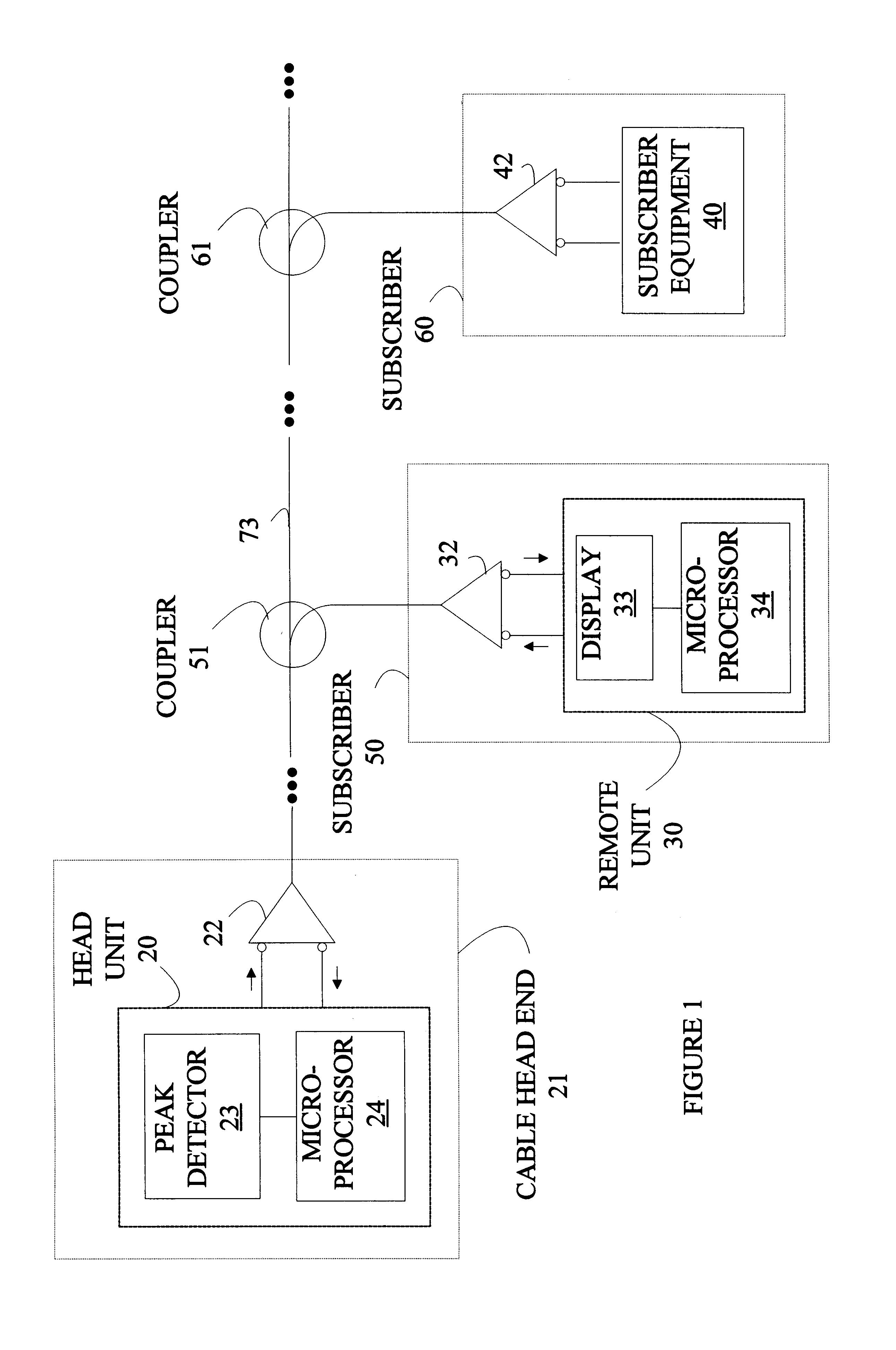
The present invention may be more easily understood with reference to FIG. 1 which is a block diagram of a cable television network to which the components of the present invention are connected. The cable 73 originates at the cable headend 21. Various subscribers are connected to the cable via couplers. Exemplary couplers are shown at 51 and 61 which connect subscribers 50 and 60, respectively. The cable supports bi-directional communication via interface units. Exemplary interface units are shown at 22, 32, and 42. Communications at each subscriber location are accomplished with the aid of modems such as modem 40.

The present invention includes two types of communication processing units. The first type of unit, referred to as a headend unit, is coupled to the cable at the cable headend. A headend unit is shown at 20. At each subscriber location being tested, a remote unit such as remote unit 30 is connected. The remote units communicate with the headend unit to initiate various te...


PUM


Abstract

A system for analyzing a bi-directional communication path connecting a headend station to a remote station. The communication path is used for sending and receiving messages. Messages in a forward direction are sent by modulating a carrier at a forward frequency, and messages sent in a return direction are sent by modulating a carrier at a return frequency. The system includes a headend unit which sends a sign-on message in the forward direction from the headend station. The headend unit monitors the return frequency for a response message and measures a power level for signals received at the return frequency during the monitoring operation. The headend unit sends an error message in the forward direction if no response message is received on the return frequency, and the power level is greater than a threshold value. If an error message is sent, the power spectrum in a frequency range including the return frequency is measured and sent as part of the error message. If no response message is detected and the power level is less than threshold, the sign-on message is repeated.

Description

FIELD OF THE INVENTIONThe present invention relates to network test systems, and more particularly, to test systems for analyzing the performance of wide area networks such as cable television networks used to provide bi-directional communications.BACKGROUND OF THE INVENTIONThe high bandwidth inherent in cable television systems makes such systems attractive candidates for providing communication links for accessing the Internet. Cable television systems provide a high bandwidth communication path for delivering information from the cable headend to the cable subscribers. While this bandwidth is currently used primarily for delivering television programming, it can also be used for delivering information received over the Internet.The typical Internet user requires a much larger incoming bandwidth than outgoing bandwidth. Typically, a user is requesting information from a server on the Internet. The amount of information returned is usually much larger than the message specifying th...

Claims


Application Information

Patent Timeline
IPC IPC(8): G06F11/00H04L12/26H04L12/28
CPCH04L43/16H04L12/2801
Inventor MORGAN, WILLIAM T.MILHOLLAND, MARVIN L.COOMES, BRENDA D.GREEN, GERALD R.WANG, CHIN-MIN
Owner AGILENT TECH INC
Learn More