Method for actuating active vibration insulators
a technology of active vibration and insulator, which is applied in the direction of vibration measurement in solids, jet propulsion mounting, internal combustion mounting, etc., can solve the problems of noise problem, minor disadvantage of quaternary or more harmonic signal components, etc., and achieve simple and less expensive effect of damping vibration of vehicle engines and inhibiting noise generation
- Summary
- Abstract
- Description
- Claims
- Application Information
AI Technical Summary
Benefits of technology
Problems solved by technology
Method used
Image
Examples
example no.1
EXAMPLE NO. 1
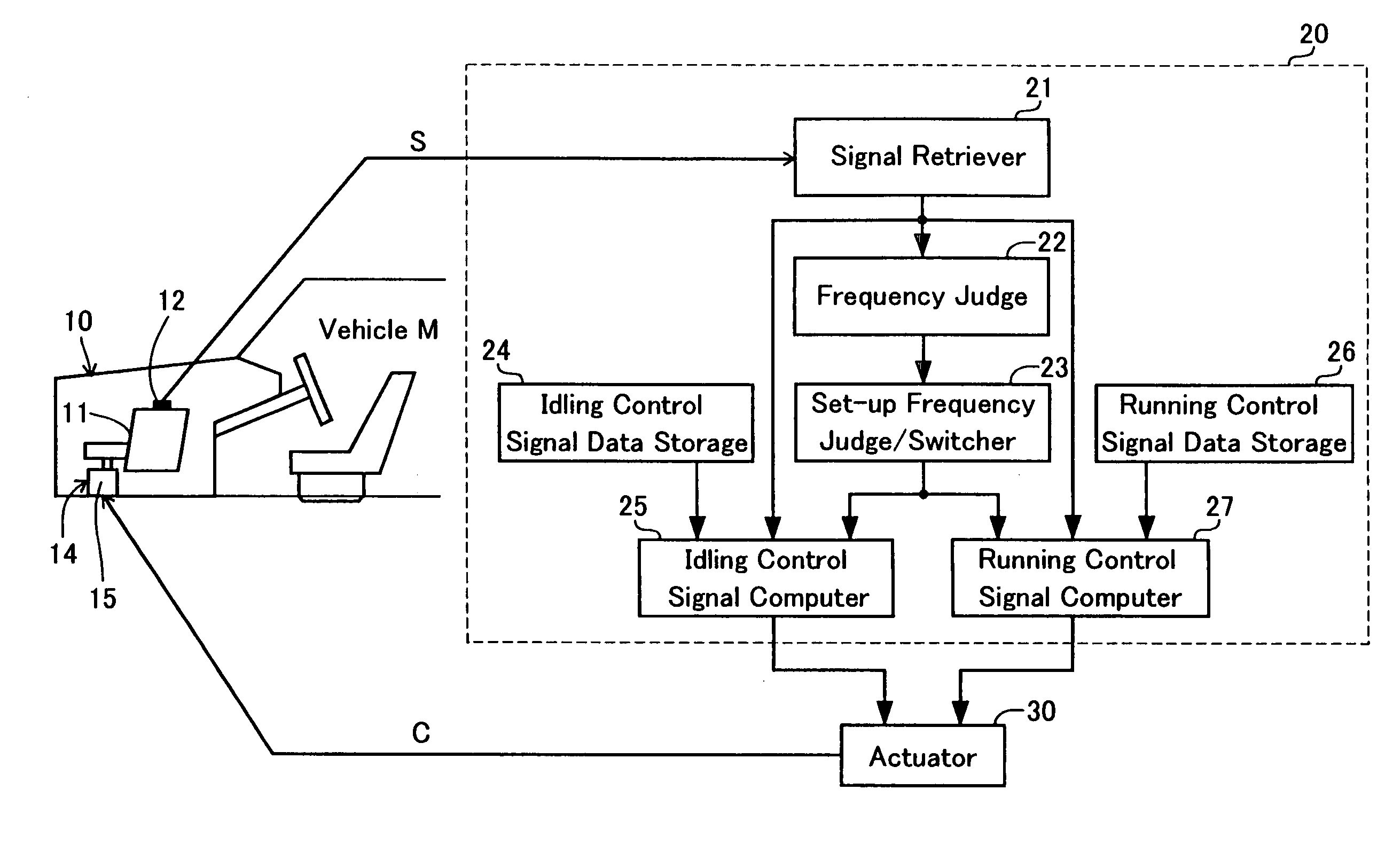
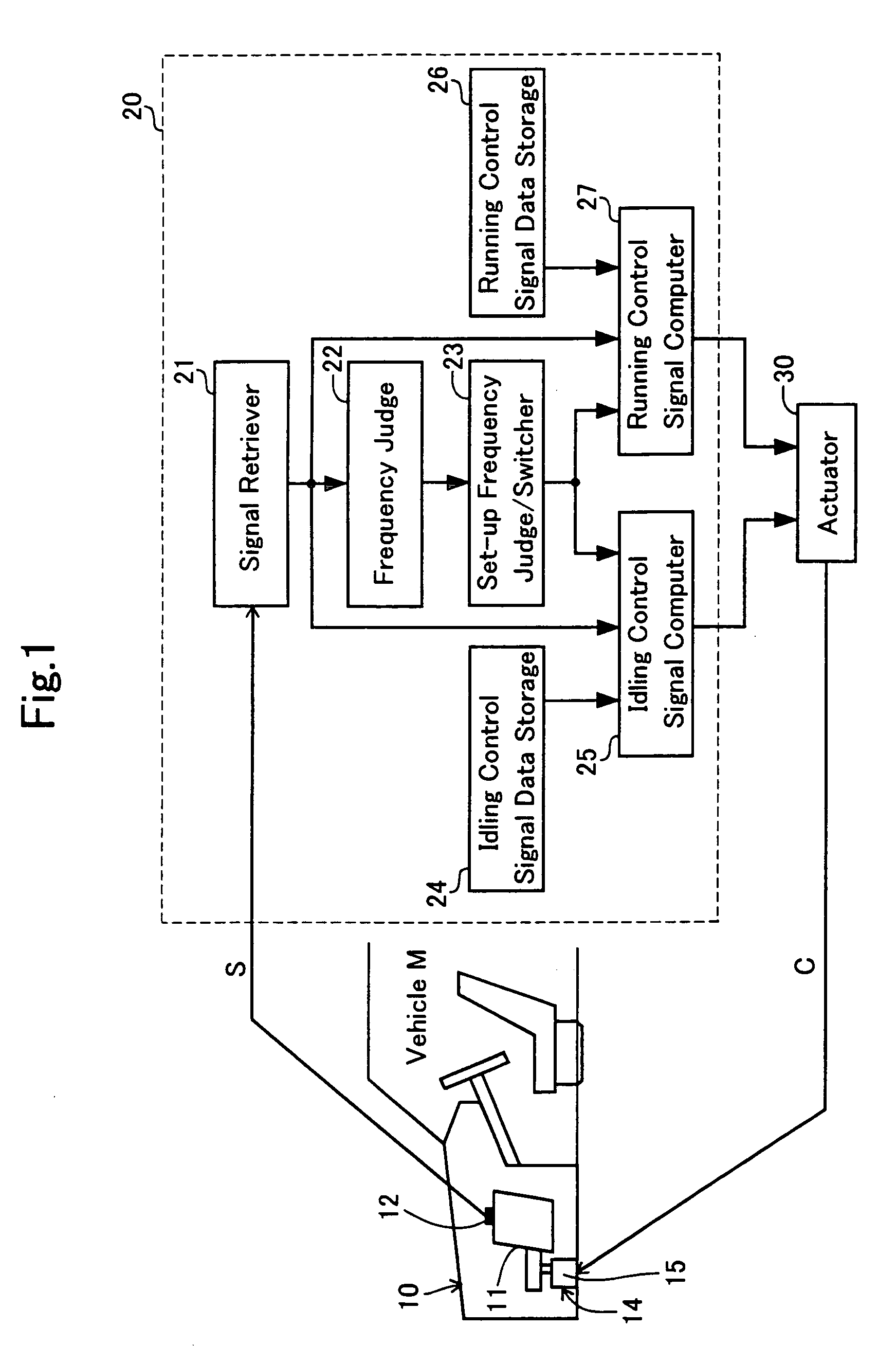
[0037]FIG. 1 roughly illustrates an arrangement of a vibration controller according to Example No. 1 of the present invention by means of a schematic diagram, vibration controller which is for inhibiting vibrations of a vehicle M's engine from transmitting. As illustrated in the drawing, the vibration controller comprises an engine mount 14, which is provided with an actuator, an active vibration insulator, (hereinafter simply referred to as an “engine mount”), a controller unit 20, and an actuator 30. The controller unit 20 generates control signals. The actuator 30 actuates an electromagnetic actuator 15 of the engine mount 14 based on the control signals. Moreover, the vehicle M comprises a vehicle body 10 which is equipped with the engine mount 14. The engine mount 14 supports an engine 11, a vibration generating source.
[0038] The engine mount 14 comprises a cylinder-shaped housing (not shown), a vibration insulator rubber (not shown) disposed in the cylinder-shape...
example no.2
EXAMPLE NO. 2
[0066] A vibration controller according to Example No. 2 of the present invention, a modified version of Example No. 1, will be hereinafter described.
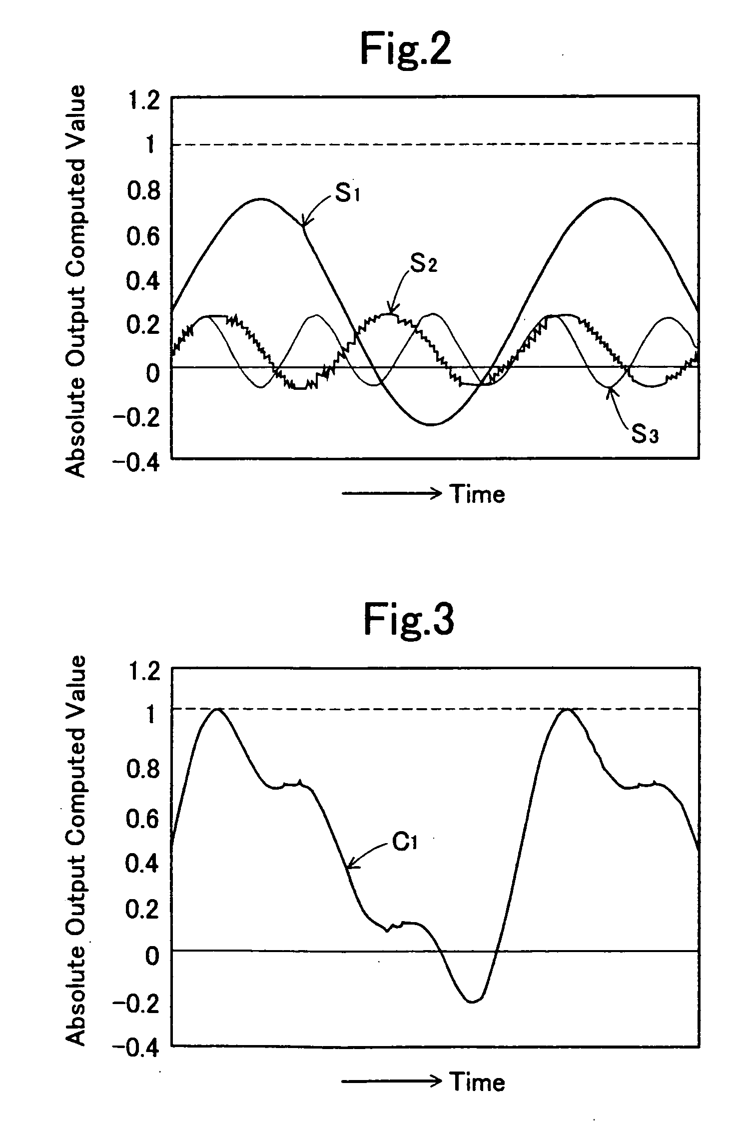
[0067] In the vibration controller according to Example No. 2 of the present invention, an idling control signal y for inhibiting the low-frequency vibrations of the engine 11 under idling from transmitting comprises a fundamental-wave signal component, a secondary harmonic signal component S2, and a tertiary harmonic signal component S3 which are superimposed one after another. Specifically, as illustrated in FIG. 6, the fundamental-wave signal component is a rectangle-shaped wave signal P1 which is expressed by following equation (5). The secondary harmonic signal component S2 and tertiary harmonic signal component S3 are sine-wave signals similarly to those of Example No. 1. Note that the notations in equation (5) are identical with those in above-described equations (2) through (4). FIG. 6 illustrates the rectangle-sh...
PUM
 Abstract
Description
Claims
Application Information
 - R&D
- Intellectual Property
- Life Sciences
- Materials
- Tech Scout
- Unparalleled Data Quality
- Higher Quality Content
- 60% Fewer Hallucinations
Browse by: Latest US Patents, China's latest patents, Technical Efficacy Thesaurus, Application Domain, Technology Topic, Popular Technical Reports.
© 2025 PatSnap. All rights reserved.Legal|Privacy policy|Modern Slavery Act Transparency Statement|Sitemap|About US| Contact US: help@patsnap.com


