Covered pinned hinge

a hinge and pinned technology, applied in the field of butt hinges, can solve the problems of reducing the size of the bearing, the cost of hinge performance, and the general appearance improvement, and achieve the effects of reducing the cost of hinge hardware, reducing the delivery time of this product, and great flexibility and buying efficiency

Inactive Publication Date: 2005-03-01
VON DUPRIN
View PDF56 Cites 32 Cited by
  • Summary
  • Abstract
  • Description
  • Claims
  • Application Information

AI Technical Summary

Benefits of technology

Another advantage of the invention is that the angular position of the cover is designed to continually bisect the angle formed by the leaves, and remain properly indexed throughout the angular travel of the leaves, or, by minor modification to the design, move slightly more in its angular relationship to one or the other of the leaves to accommodate any special geometrical or appearance requirements that might be encountered in certain installations.
is that the angular position of the cover is designed to continually bisect the angle formed by the leaves, and remain properly indexed throughout the angular travel of the leaves, or, by minor modification to the design, move slightly more in its angular relationship to one or the other of the leaves to accommodate any special geometrical or appearance requirements that might be encountered in certain installations.
Yet another advantage of the invention is that the covering member may be designed for installation or replacement by the distributor or at the jobsite. This means that the manufacturer does not need to be concerned with the color or material of the final product at the outset. The distributor is likewise able to use his inventory with the greatest flexibility and buying efficiency by purchasing the hinge “chassis” in large quantities, and assembling a cover of the user's choice at the point of sale.
Another advantage of the invention is the greatly reduced cost of hinge hardware which would otherwise require manufacture in costly materials, which are often not suitable for high-stress applications. For example, a “brass” hinge could be made with inexpensive, painted or plated steel leaves and equipped with a cover in polished brass, brushed brass, or brass with an “antiqued” or bronze color. Such a hinge would be far stronger and manufactured at a fraction of the cost of a solid brass hinge. Further, the delivery time for this product would be drastically reduced by combining a standard, mass-produced hinge “chassis” with any one of a variety of inexpensive covers in any desired color or material, including plated, polished or brushed metal, or plastics. The hinge “chassis” can be equipped with whatever number of joints and bearings are best suited for the service requirements of the application without regard to the outward appearance of its mechanical design, which will be covered along its entire length. Clearly, the possibilities for improved hinge appearance at very low cost are unique with this invention, which at the same time makes it possible, for the first time, to paint a hinge repeatedly without fear of chipping at the joints, or to clad it with wallpaper or even a wood veneer without consequence.
A pinned hinge formed according to principles of the present invention comprises first and second hinge members and a cover. The first and second hinge members may be pivotally connected by a pin having two ends. At least one end of the cover may be mechanically coupled with one end of a pin. In one embodiment, at least one gear is disposed on one end of the pin to mechanically couple the cover to the pin. Preferably, the gear in one embodiment has a gear segment comprising gear teeth extending partially around the circumference and outer surface of the gear. In another embodiment, at least one end of the cover has a gear rack to engage the at least one gear disposed on one end of the pin. In yet another embodiment, the end of the cover may have an end cap in which the gear rack is disposed.
The hinge members may each have a leaf for attachment to a hinged object and at least one knuckle in which a pin may be received. The knuckles may have passageways which are preferably axially aligned with the other knuckles of a hinge member. When the hinge is assembled by joining the first and second hinge members together, the passageways of the first and second hinge members are preferably substantially coaxially aligned for insertion of the pin through both members.

Problems solved by technology

Improvements in appearance have generally been limited to reducing the number of joints which occur between the interposed leaves, or reducing the size of the bearings, often at the expense of hinge performance.
Thrust bearings, or combinations of radial and thrust bearings are most often visible between the knuckles, adding to the complexity of the design and often compromising the appearance of the hinge.
However, only half the number of installed bearings actual carry the weight of the door, because the other two are located on those knuckle surfaces which tend to separate rather than compress when the door is installed.
Such hinges are thought to be a further improvement in appearance, but they must be manufactured in both left- and right-hand versions so that they can carry doors of either “hand.” This makes manufacturing and distribution more complex, because incorrect specification resulting in delays and consequential added costs often accompanies such products.
Clearly, the trend toward the elimination of unsightly joints has fostered the development of butt hinges with ever-fewer knuckles, even at greater cost, inconvenience, and degradation of hinge performance.

Method used


Image

  • Covered pinned hinge
  • Covered pinned hinge
  • Covered pinned hinge

Examples


Embodiment Construction

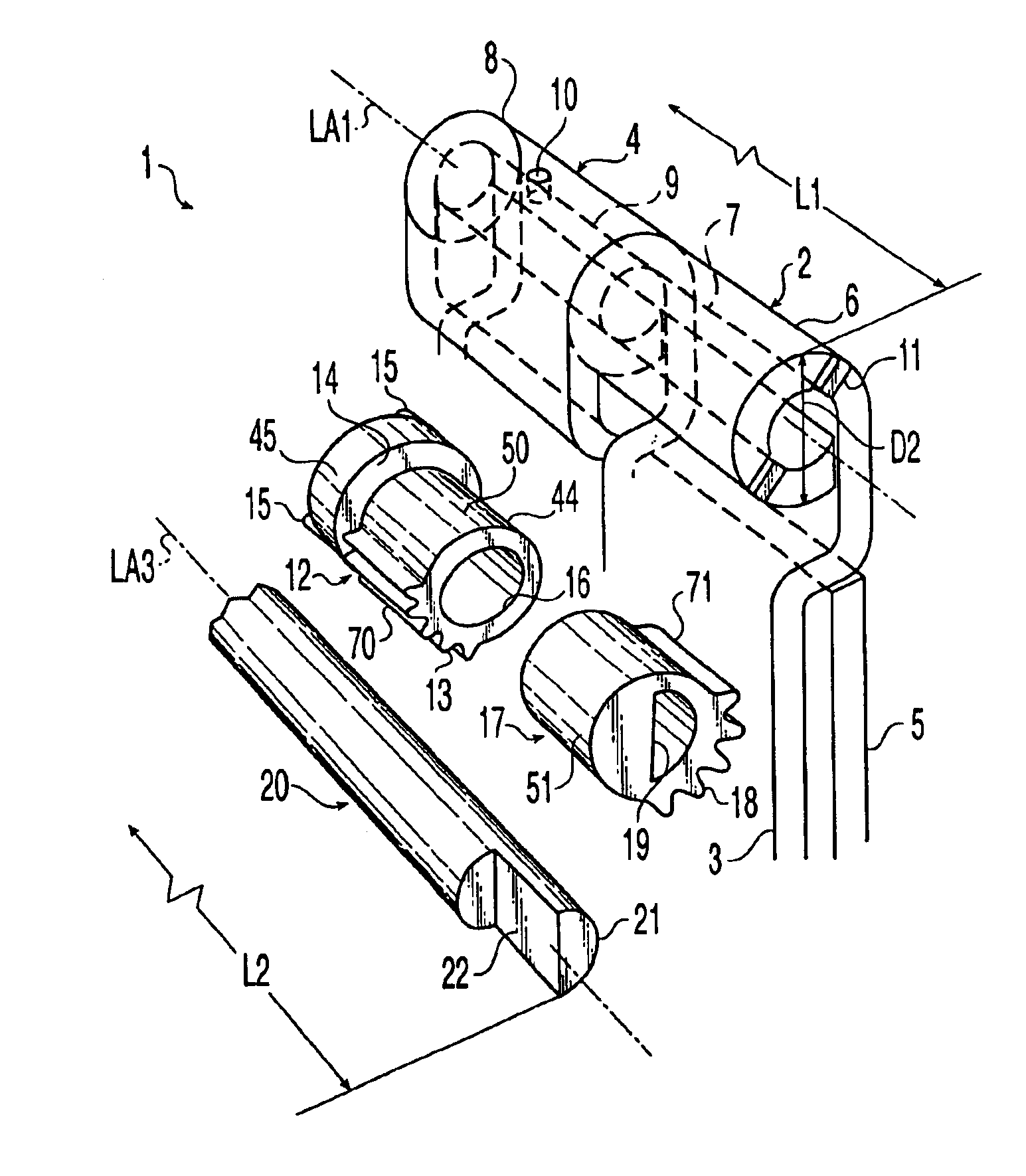
Referring to FIG. 1, a pinned hinge 1 having a mechanically articulated cover is depicted in one embodiment as including at least two hinge members 2, 4. The hinge members 2, 4 each comprise knuckles or barrels 6, 8 and leaves 3, 5 connected thereto, respectively. In one preferred embodiment (shown in FIGS. 6-8), a five knuckle hinge 1 is provided in which hinge member 2 has three knuckles 6 and hinge member 4 has two knuckles 4, which are interspersed between the knuckles 6 of hinge member 2. A total hinge length L1 (as shown in FIGS. 1 and 6) is defined as the total length through the knuckle portions of the hinge members 2, 4 after the hinge has been assembled, including the contributions to the total length by any bearings or other structures that may be located in the joints between adjacent knuckles.

The knuckles 6, 8 have passageways 7, 9 which extend longitudinally through the knuckles and define a longitudinal axis LA1 through the knuckles 6, 8 and pinned hinge 1. The passag...


PUM


Abstract

A slim profile covered pinned hinge is provided which comprises a first hinge member, a second hinge member, and a mechanically articulated cover. The first and second hinge members are pivotally connected by a pin. The first and second hinge members may each further comprise a leaf for attachment to a hinged object, a door or door jamb for example, and at least one knuckle through which the pin may be received. The cover may be elongated and has an internal cavity, thereby allowing the cover to be slipped over the hinge concealing the knuckles and joints therebetween of the hinge members. The cover has two ends and may be mechanically coupled to the pin at one or both ends. In one embodiment, at least one end of the pin may have at least two gears comprising a gear segment. The ends of the cover may have at least one gear rack to engage the gears on the end of the pin. Angularly opening and closing the first and second hinge members moves the cover with respect to the pin, providing additional clearance to allow for the leaves of the hinge members to swing as the hinge is operated.

Description

BACKGROUND OF THE INVENTIONThe present invention generally relates to butt hinges, and more particularly, to an improved covered and pinned butt hinge with a slimmer appearance.The butt hinge, also known as a mortise hinge because it is normally mortised or inset into the door jamb (frame) and into the edge of the door, is well-known in the hardware industry. Over the years, many improvements have been made to both improve its longevity and to improve its appearance. Among the developments that enhance the service life of butt hinges, particularly those used in commercial applications, is the inclusion of bearings of different kinds to reduce friction. Bronze bearings, ball bearings and friction-resistant plastic bearings have all been successfully used. Improvements in appearance have generally been limited to reducing the number of joints which occur between the interposed leaves, or reducing the size of the bearings, often at the expense of hinge performance.The most common hinge...

Claims


Application Information

Patent Timeline
Patent Type & Authority Patents(United States)
IPC IPC(8): E05D3/00E05D3/02E05D7/00E05D3/18
CPCE05D3/022E05D7/009Y10T16/533E05Y2900/132Y10T16/541E05Y2201/71
Inventor BAER, AUSTIN R.
Owner VON DUPRIN
Why Eureka
Try Eureka