Process and apparatus for grinding work for non-circular rotor, as well as camshaft

a technology of non-circular rotors and grinding machines, which is applied in the direction of edge grinding machines, grinding machine components, manufacturing tools, etc., can solve the problems of reduced indexing accuracy, difficult shortening of grinding time, and reduced standard phase indexing accuracy, so as to achieve good camshaft appearance and simplify the manufacture of blanks

Inactive Publication Date: 2006-07-27
MUSA PRECISION IND CO LTD
View PDF9 Cites 9 Cited by
  • Summary
  • Abstract
  • Description
  • Claims
  • Application Information

AI Technical Summary

Benefits of technology

[0016] With the fifth feature, when a blank for the camshaft is to be fabricated, it is unnecessary to form a recess indicating the standard phase in an outer peripheral surface of the blank. Thus, the fabrication of the blank can be simplified, and a good appearance of the camshaft can be provided.

Problems solved by technology

However, to fit the movable element of the standard phase sensor into the recess, a fitting clearance must be provided between the recess and the sensor and is one cause of a reduction in accuracy of indexing of the standard phase of the work.
The reduction in indexing accuracy compels an increase in grinding margin of the work and as a result, it is difficult to shorten the grinding time.

Method used


Image

  • Process and apparatus for grinding work for non-circular rotor, as well as camshaft
  • Process and apparatus for grinding work for non-circular rotor, as well as camshaft
  • Process and apparatus for grinding work for non-circular rotor, as well as camshaft

Examples


first embodiment

[0040] The operation of the first embodiment will be described below.

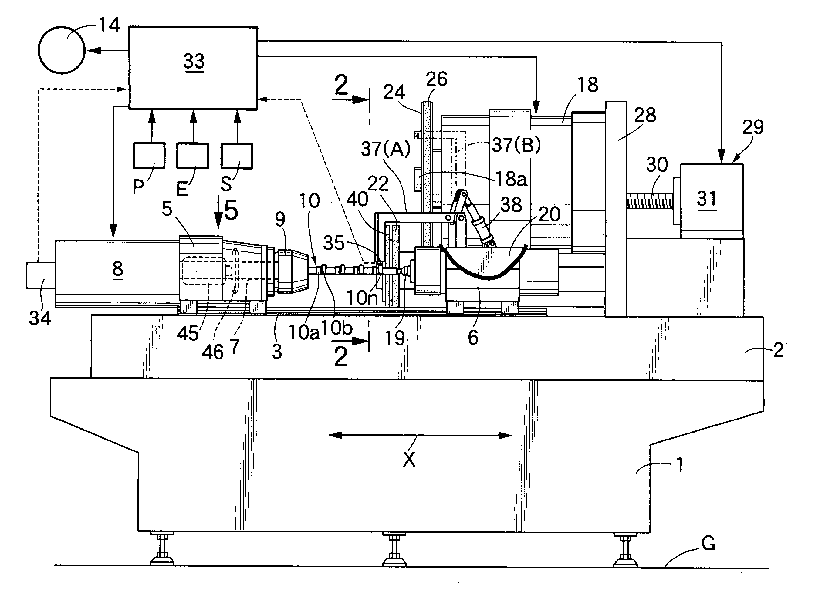
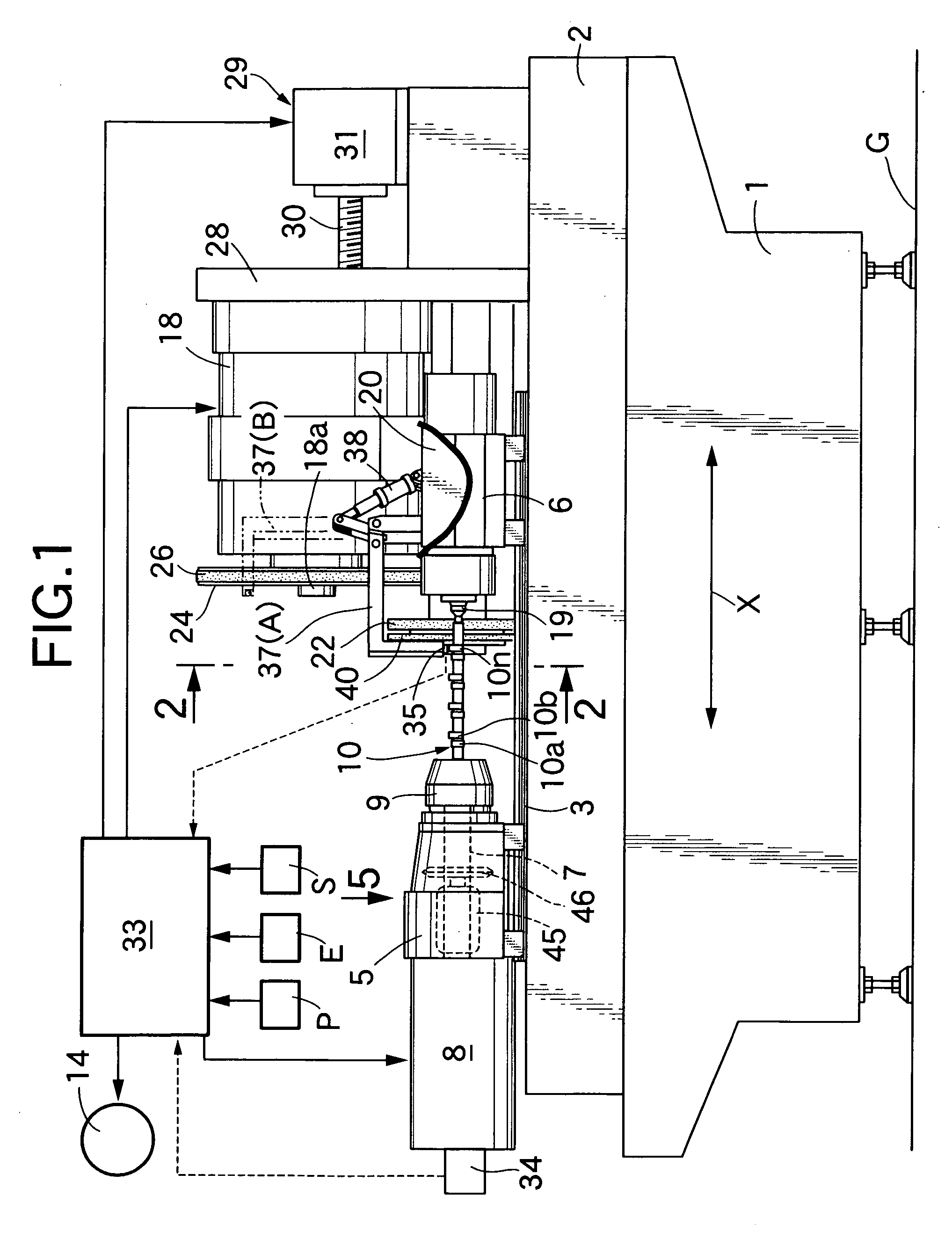
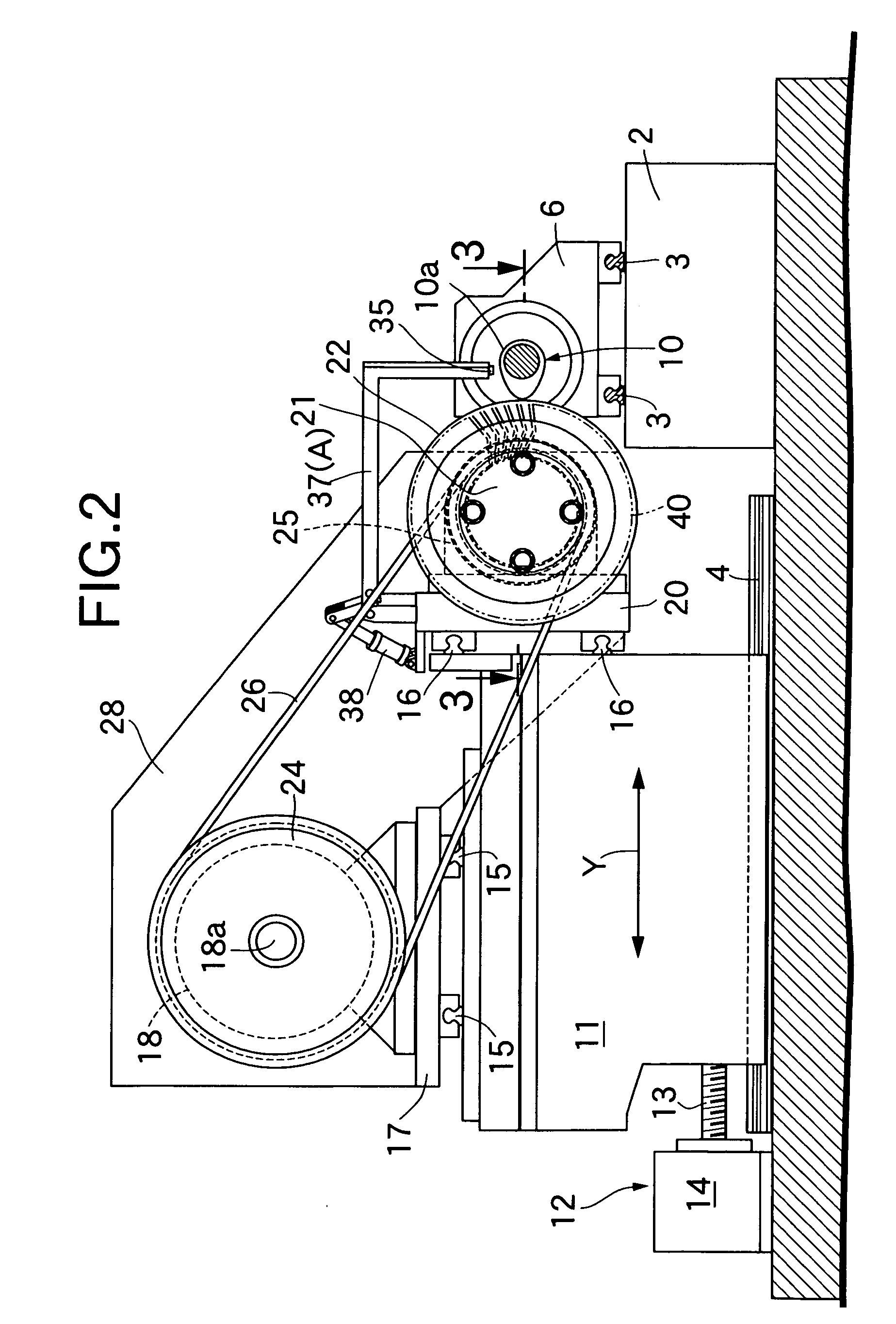
[0041] First, to carry out the dressing of the rotary grindstone 22, the outer peripheral surface of the rotary grindstone 22 rotated along with the wheel spindle 21 is brought into contact with the diamond dresser 46 and fed axially, while rotating the wheel spindle 21 at a low speed by the operation of the third electric motor 18 in a state in which the diamond dresser 46 is being rotated at a high speed by the operation of the dressing motor 45, as shown in FIG. 5.

[0042] During such dressing of the rotary grindstone 22, the rotational speed of the wheel spindle 21 is relatively low and hence, each of the wires 42 of the deflashing brush 40 is in contracted state and thus, the diameter of the deflashing brush 40 is smaller than that of the rotary grindstone 22. Therefore, it is possible to avoid the interference of the deflashing brush 40 with the diamond dresser 46.

[0043] Now, to grind the outer peripheral sur...

second embodiment

[0051] the present invention shown in FIG. 8 will now be described.

[0052] The second embodiment is different from the previous embodiment in respect of the construction of a deflashing brush 40. More specifically, through-bores 44, 44 are made in a brush body 41 and arranged circumferentially in a large number of sets with the adjacent two thereof disposed in a V-shape on opposite sides of a radius line R to form a pair. Two tip ends of a wire 42 bent into a V-shape at its central portion are inserted through each of the pairs of the through-bores 44, 44 from the side of an inner periphery of the brush body 41, and the wire 42 is brazed in each of the through-bores 44. The wire 42 bent into the V-shape is inclined with respect to the radius line R of the brush body 41 in its free state, so that its tip end is located radially inside the outer peripheral surface of the rotary grindstone 22, as shown by a solid line in FIG. 8. However, when the wheel spindle 21 is brought into a prede...


PUM

PropertyMeasurementUnit
constant curvature radiusaaaaaaaaaa
distancesaaaaaaaaaa
axial distancesaaaaaaaaaa

Abstract

To grind an outer peripheral surface of a work (10) for a non-circular rotor by a rotary grindstone (22) advanced and retreated by an NC control depending on the profile of the work (10), while rotating the work (10) about its axis, the following steps are carried out: a first step of detecting a predetermined lift amount of the outer peripheral surface of the work (10) at a given point to index a standard phase of the work (10); and a second step of advancing or retreating a grindstone 22 by the NC control depending on a standard phase of the work (10) indexed at the first step to grind the outer peripheral surface of the work (10). Thus, even if a special recess is not formed in the outer periphery of the work, the indexing of the standard phase of the work can be achieved properly.

Description

FIELD OF THE INVENTION [0001] The present invention relates to an improvement in a process for grinding a work for a non-circular rotor for grinding an outer peripheral surface of the work by a rotary grindstone advanced and retreated by an NC control depending on the profile of the work, while rotating the work for the non-circular rotor about an axis thereof, and also relates to an apparatus for grinding a work for a non-circular rotor, comprising a work-rotating means for rotating the work for the non-circular rotor about the axis, while supporting the work, a rotary grindstone capable of grinding an outer peripheral surface of the work, grindstone-rotating and reciprocally moving means capable of being advanced and retreated with respect to the outer peripheral surface of the work, while driving the rotary grindstone in rotation, a standard phase-indexing means for indexing a standard phase of the work, and an NC control unit for advancing and retreating the rotary grindstone to...

Claims


Application Information

Patent Timeline
Patent Type & Authority Applications(United States)
IPC IPC(8): B24B51/00B24B1/00B24B7/19B23Q15/26B24B9/00B24B19/08B24B19/12B24B29/00B24B49/10
CPCB23Q15/26B24B9/00B24B19/08B24B29/005
Inventor MURAI, FUKUO
Owner MUSA PRECISION IND CO LTD
Why Eureka
Try Eureka