
Method and apparatus for measuring a variable in a lubricant/coolant system

a technology of fluid system and variable, applied in the direction of instruments, manufacturing tools, material analysis, etc., can solve the problems of many sensors subject to fouling, the method and the apparatus addressing specific operational problems such as accurate measurement of fluid variables such as ph, concentration, conductivity or temperature have not been fully developed, etc., to achieve accurate measurement of sensed variables

Inactive Publication Date: 2005-03-01
MASTER CHEM
View PDF10 Cites 17 Cited by
  • Summary
  • Abstract
  • Description
  • Claims
  • Application Information

AI Technical Summary

Benefits of technology

It is a further object of the present invention to provide an apparatus for monitoring at least one variable of a machine coolant or lubricant.
Thus it is an object of the present invention to provide a method for monitoring at least one variable of a machine coolant or lubricant.
It is a still further object of the present invention to provide a method and apparatus for cleaning and checking calibration of a fluid variable sensor.
It is a still further object of the present invention to provide a method and apparatus for cleaning and checking calibration of a fluid variable sensor for machine coolants and lubricants.
It is a still further object of the present invention to provide monitoring of at least one variable of machine coolants and lubricants and provide such information to a remotely located site.

Problems solved by technology

Moreover, it is apparent that methods and apparatus addressing particular operational problems such as accurate measurement of a fluid variable such as pH, concentration, conductivity or temperature have not been fully developed.
For example, many sensors are subject to fouling when exposed to coolants and lubricants and particularly so when the coolants and lubricants become contaminated.

Method used


Image

  • Method and apparatus for measuring a variable in a lubricant/coolant system
  • Method and apparatus for measuring a variable in a lubricant/coolant system
  • Method and apparatus for measuring a variable in a lubricant/coolant system

Examples


Embodiment Construction

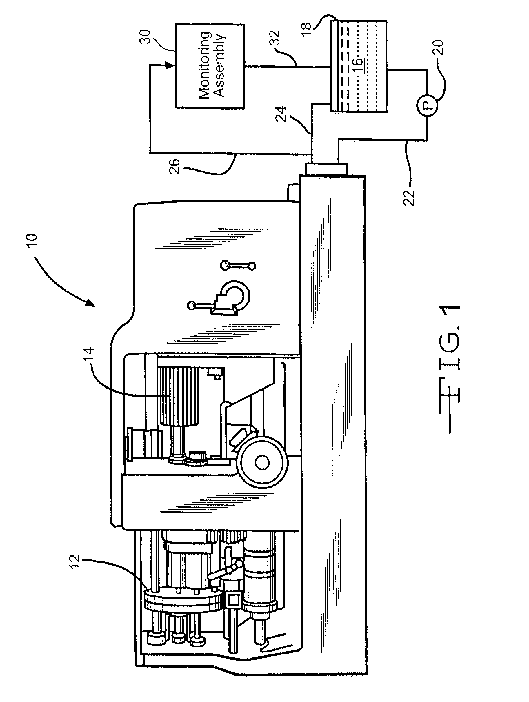
Referring now to FIG. 1, an automatic screw machine 10 incorporates various carriages 12 and magazines 14 for workpieces and tools which cooperate to manufacture various and sundry machine parts (not illustrated). It is to be understood that the automatic screw machine 10 is illustrative only and that the apparatus and method of the present invention may be and is intended to be utilized with such automatic screw machines 10, computer numerical controlled (CNC) devices and machining centers, lathes, grinders, milling machines, and all manner of equipment for cutting, forming, boring, milling, drilling and shaping of typically though not exclusively metal parts wherein the aforementioned processes are facilitated by application of cooling and / or lubricating fluids 16.

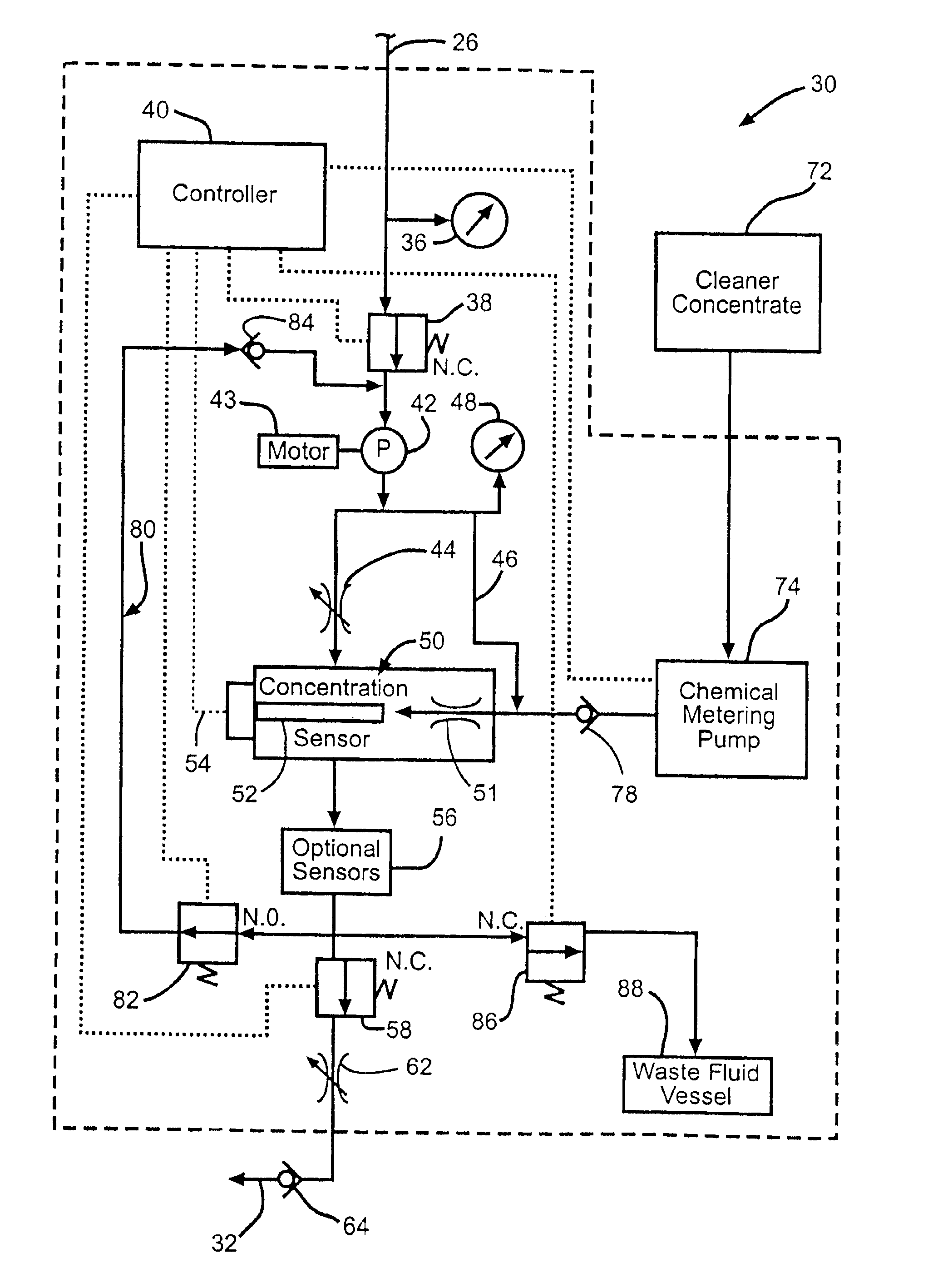
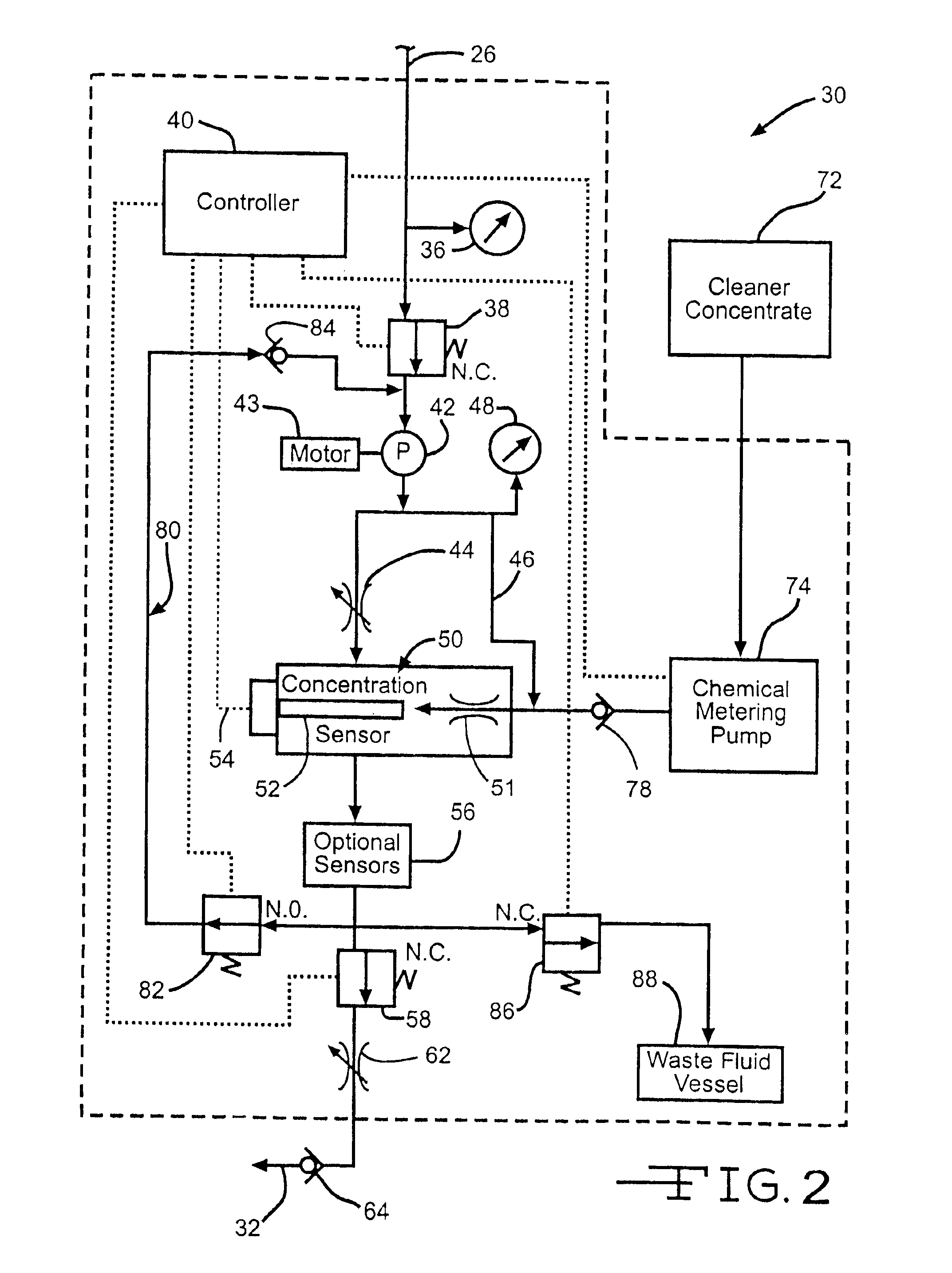
Such cooling and lubricating fluids 16 are typically stored in a sump 18 and may be supplied to the machine 10 under pressure by a pump 20 in a line 22. A return line 24 provides the cooling and lubricating fluid 16 dire...


PUM

PropertyMeasurementUnit
diameteraaaaaaaaaa
concentrationaaaaaaaaaa
concentrationsaaaaaaaaaa

Abstract

An automatic system for monitoring / controlling a variable of a machine or metalworking fluid system also achieves cleaning and optionally, a calibration check of the sensor of the variable. The system includes one or more sensors for variables such as pH, fluid concentration, conductivity, temperature and the like, a supply of a cleaning agent and associated valves and conduits for connecting the automatic system to a fluid to be measured. A cleaning cycle can be scheduled as necessary to clean and / or check calibration of the sensors and ensure accurate measurement of sensed variables. If desired, the data regarding the sensed variables may be utilized to perform corrective action in real time.

Description

BACKGROUND OF THE INVENTIONThe invention relates generally to a method and apparatus for measuring a variable in a fluid system and more particularly to a method and apparatus for measuring a fluid variable in a lubricant or coolant system and cleaning and undertaking a calibration check of the measurement device to ensure accurate measurement.Most machine tools that remove metal, including automatic screw machines and computer controlled machining centers rely upon cooling and lubricating fluids applied to the machining site to improve tool life, enhance the surface finish of the machined region, increase cutting speeds and remove heat from the machining process to minimize distortion of the part and interference with or reduction of properties achieved by heat treatment.Maintaining optimum concentrations and fluid characteristics of such cooling and lubricating fluids is desirable from the standpoints of maintaining optimum machining conditions, maximizing coolant and lubricant se...

Claims


Application Information

Patent Timeline
Patent Type & Authority Patents(United States)
IPC IPC(8): B21B45/02G01N33/00G01N35/00G01N33/30
CPCG01N33/30G01N33/2894
Inventor SEEVERS, STANLEY W.HUGHES, GUY R.ROBINSON, FRANK A.
Owner MASTER CHEM
Learn More