Combined in-plane shear and multi-axial tension or compression testing apparatus

a technology of multi-axial tension and compression testing, which is applied in the direction of measurement devices, material strength using repeated/pulse forces, instruments, etc., can solve the problems of complex responses, unrefined structure technology, and difficult to analyze reliable structures. achieve the effect of increasing the distance between the corresponding load transfer plate and providing flexibility

Active Publication Date: 2005-03-01
THE UNITED STATES OF AMERICA AS REPRESENTED BY THE SECRETARY OF THE NAVY
View PDF15 Cites 115 Cited by
  • Summary
  • Abstract
  • Description
  • Claims
  • Application Information

AI Technical Summary

Benefits of technology

The apparatus also provides flexibility by the ability to apply an unequal stress state or multi-axial load to the test specimen by utilizing load transfer plates of different lengths. Additionally, the apparatus provides flexibility by the ability to apply a non-orthogonal multi-axial loading by utilizing a different angle, other than exact angles between the vertices of the four-bar linkages. The angle of rotation of the linkages between the vertices can be measured directly by the test machine through load cells or other conventional instrumentation.
More specifically in structure, the apparatus comprises two four-bar linkages for biaxial testing and capable of the addition of other four-bar linkages for testing along additional axes. The four-bar linkages defining a rhombus-shape are pivotally connected to one another at opposing ends or vertices by sleeve bearings positioned at each vertex. The sleeve bearings at each vertex are axially connected to one another with a pin and thrust bearings between the

Problems solved by technology

Although, the structures are well-known in the art, the technology for the structures has not been refined such that reliable structures can be analytically designed.
Presently, modeling the mechanical properties of woven fabrics results in complex responses because of the complex microstructures of the composite materials used.
While biaxial testing apparatuses with compression and tension loading or in-plane shear testing apparatuses exist in the prior art, there are no apparatuses that exist with a combined feature of in-plane shear and compression/testing capabilities.
Also, a testing apparatus does not exist that is capable of applying non-orthogonal multi-axial loading.
An apparent disadvantage is the need for two or more loading devices and the associated high cost of equipment.
A restrictive disadvantage of the apparatus is the requirement of the cylindrical shape of the specimen and

Method used


Image

  • Combined in-plane shear and multi-axial tension or compression testing apparatus
  • Combined in-plane shear and multi-axial tension or compression testing apparatus
  • Combined in-plane shear and multi-axial tension or compression testing apparatus

Examples


Embodiment Construction

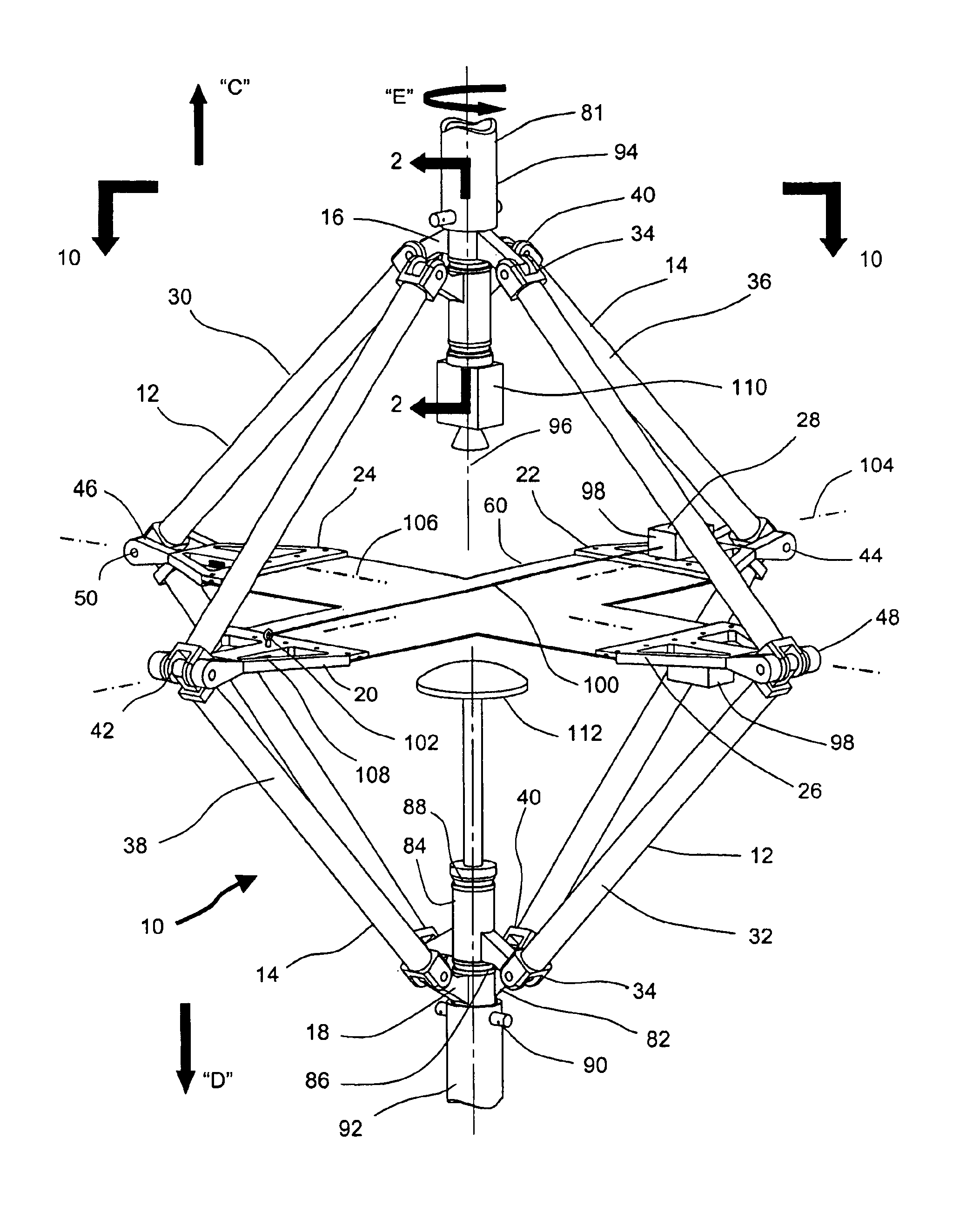
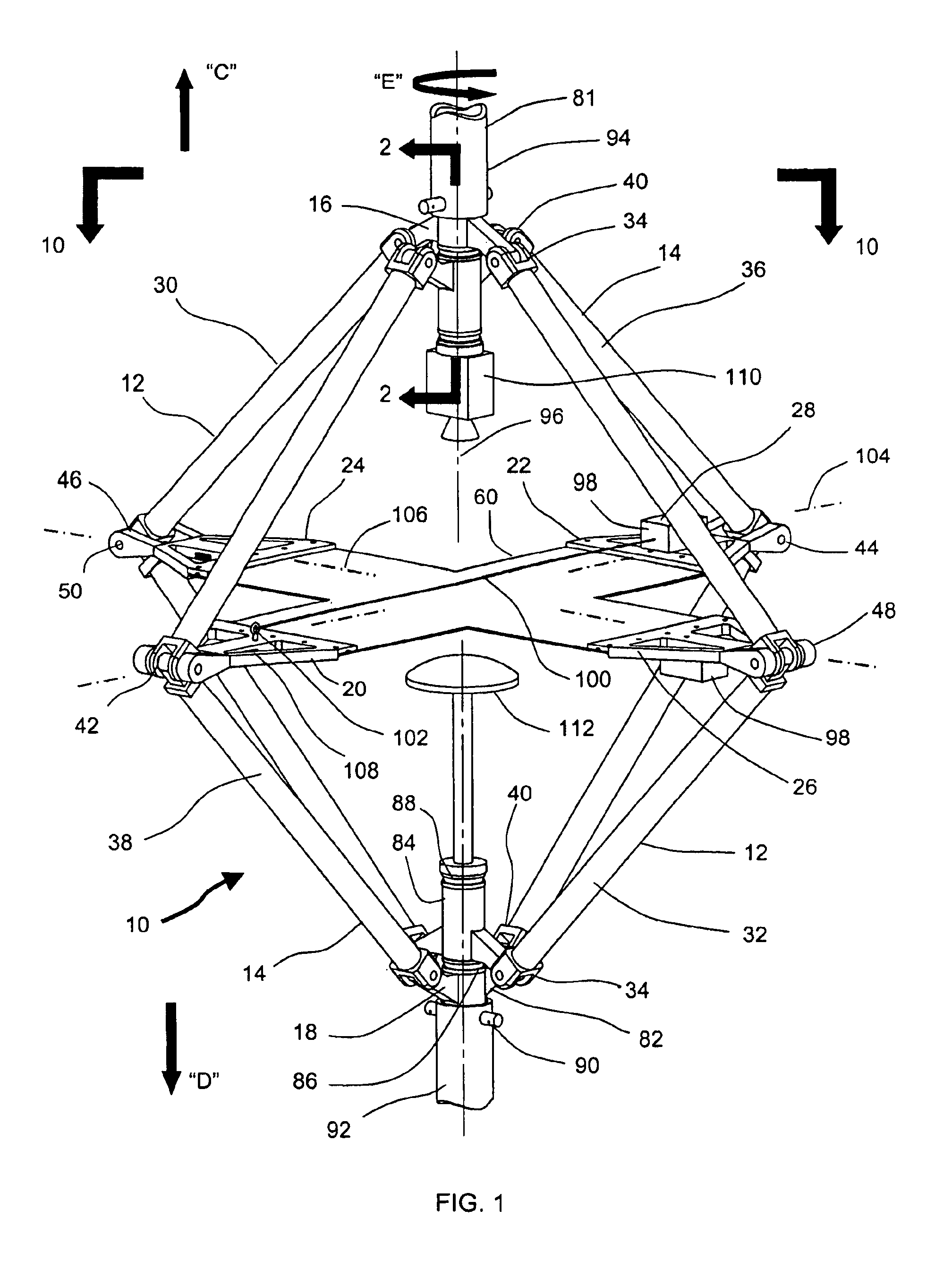
Referring now to the drawings wherein like numerals refer to like elements throughout the several views, one sees that FIG. 1 depicts a preferred embodiment of a testing apparatus 10 of the present invention. As shown in the figure, the apparatus 10 for biaxial loading generally comprises four-bar linkages 12 and 14 defining a perimeter of a variable rhombus shape, a first (or as shown) a top joint assembly 16, a second (or as shown) a bottom joint assembly 18, load transfer plates 20, 22, 24 and 26 and an associated strain and displacement measurement system 28.

The linkage 12 includes two pairs of oblong and rigid members 30 and 32. Each end of each member is rigidly connected to a bracket 34 in which each bracket is pivotally connected to the top joint assembly 16 and the bottom joint assembly 18. The linkage 14 includes two pairs of oblong and long rigid members 36 and 38. Each end of each member is rigidly connected to a bracket 40 in which each bracket is pivotally connected to...


PUM


Abstract

An in-plane shear and multi-axial tension or compression testing apparatus having four-bar linkages pivotable to two sleeves on an opposite vertices with the sleeves of each vertex rotationally attached to each other. Lateral links of each linkage are pivotally attached to load transfer plates in which the plates secure a test specimen. Each linkage is rotatable to the other linkages while the vertices are subjected to a compression or tensile load. The vertices are also capable of rotation by a testing machine for shear testing. During compression or tension of the vertices of the apparatus, the plates respectfully move toward or away from each other thereby applying compression or tension to the specimen. The bars of one linkage can be rotated with respect to the other, thereby applying torsional loading to the specimen.

Description

BACKGROUND OF THE INVENTION(1) Field of the InventionThe present invention relates to a combined in-plane shear loading and multi-axial tension or compression testing apparatus in which the apparatus is capable of determining the mechanical properties of metals, plastics, woods, fabrics, elastomers and other materials.(2) Description of the Prior ArtPlain-woven fabrics are widely utilized as structural materials in air-inflated structures and rapidly deployable structures such as temporary shelters, tents, temporary bridges and space structures. Unlike metallic structures, these structures are primarily designed to be lightweight, self-erecting and deployable to volume-storage ratios that may be 1000-to-1. Air-inflated structures utilize pressurized fabric tubes and pressure-stabilized beams (known as air beams) as load-carrying members.Although, the structures are well-known in the art, the technology for the structures has not been refined such that reliable structures can be anal...

Claims


Application Information

Patent Timeline
IPC IPC(8): G01N3/08G01N3/00G01N3/02
CPCG01N3/08G01N2203/0256
Inventor CAVALLARO, PAUL V.QUIGLEY, CLAUDIA J.SADEGH, ALI M.
Owner THE UNITED STATES OF AMERICA AS REPRESENTED BY THE SECRETARY OF THE NAVY
Why Eureka
Try Eureka