Walk-behind tiller

a technology of walking behind and forming a handle, which is applied in the direction of agricultural machines, cell components, adjusting devices, etc., can solve the problems of increasing production costs, increasing the number of components, and difficulty in reducing production costs, so as to improve the operability

Inactive Publication Date: 2005-03-01
HONDA MOTOR CO LTD
View PDF19 Cites 13 Cited by
  • Summary
  • Abstract
  • Description
  • Claims
  • Application Information

AI Technical Summary

Benefits of technology

For working the soil with the tiller, the handle is lifted to cause the tilling device to dig into the traveling surface. At that time, the operator can put the fingers on the lever forward-tilted portions while putting the hands on the left and right rising portions of the handle and hold the rising portions and the lever forward-tilted portions of the clutch lever together. Thus, for manually operating the clutch lever for working the soil, it is not necessary to change the current positions of the hands holding the rising portions of the handle.
The clutch lever of the tiller according to the present invention has the left and right lever forward-tilted portions having a shape corresponding to the shape of the left and right rising portions of the handle, so that the lever forward-tilted portions are positioned in proximity to the rising portions of the handle, resulting in improved operability.

Problems solved by technology

The above vertical position adjustment configuration consists of a number of components and is thus complicated, making it difficult to reduce production costs.
This results in the problem that the effect of forming the handle 100 in a loop cannot be exerted.
While the above tiller 200 provided with the handle height adjustment lever 213 can improve the work posture of an operator, it has the problem of an increased number of components and increased production costs.
The two clutch levers 302, 303 are provided in proximity but are so far from a handle grip 300a that it is required to unhand the handle grip 300a to switch the clutch levers 302, 303 from off to on, resulting in the problem of reduced clutch operability.

Method used


Image

  • Walk-behind tiller
  • Walk-behind tiller
  • Walk-behind tiller

Examples


Embodiment Construction

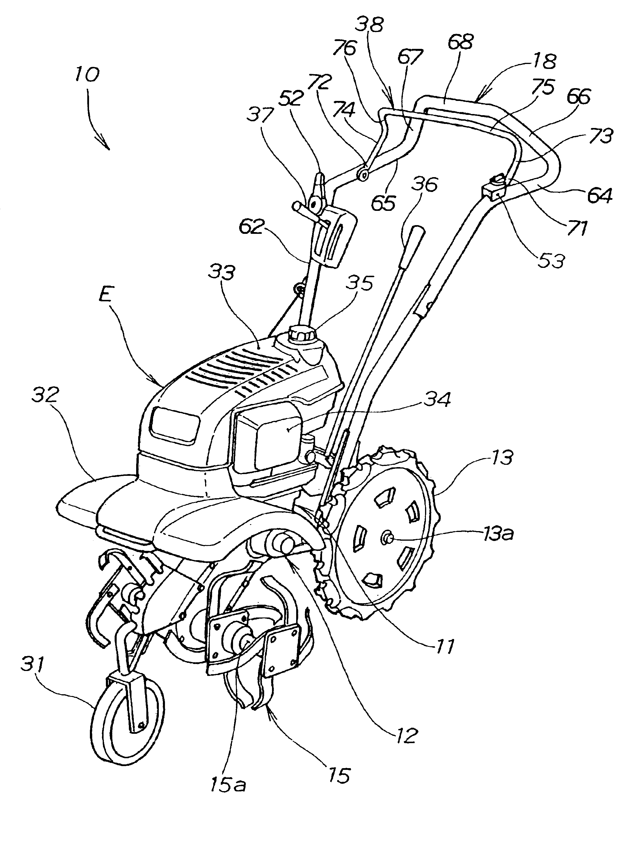
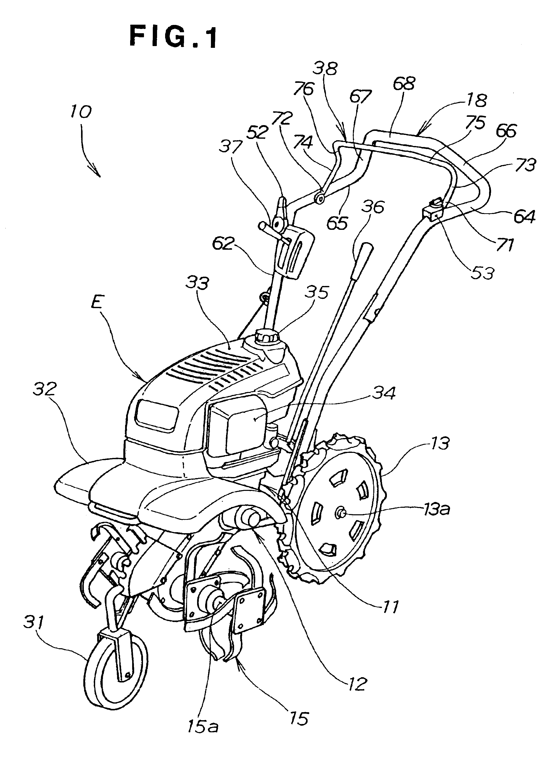
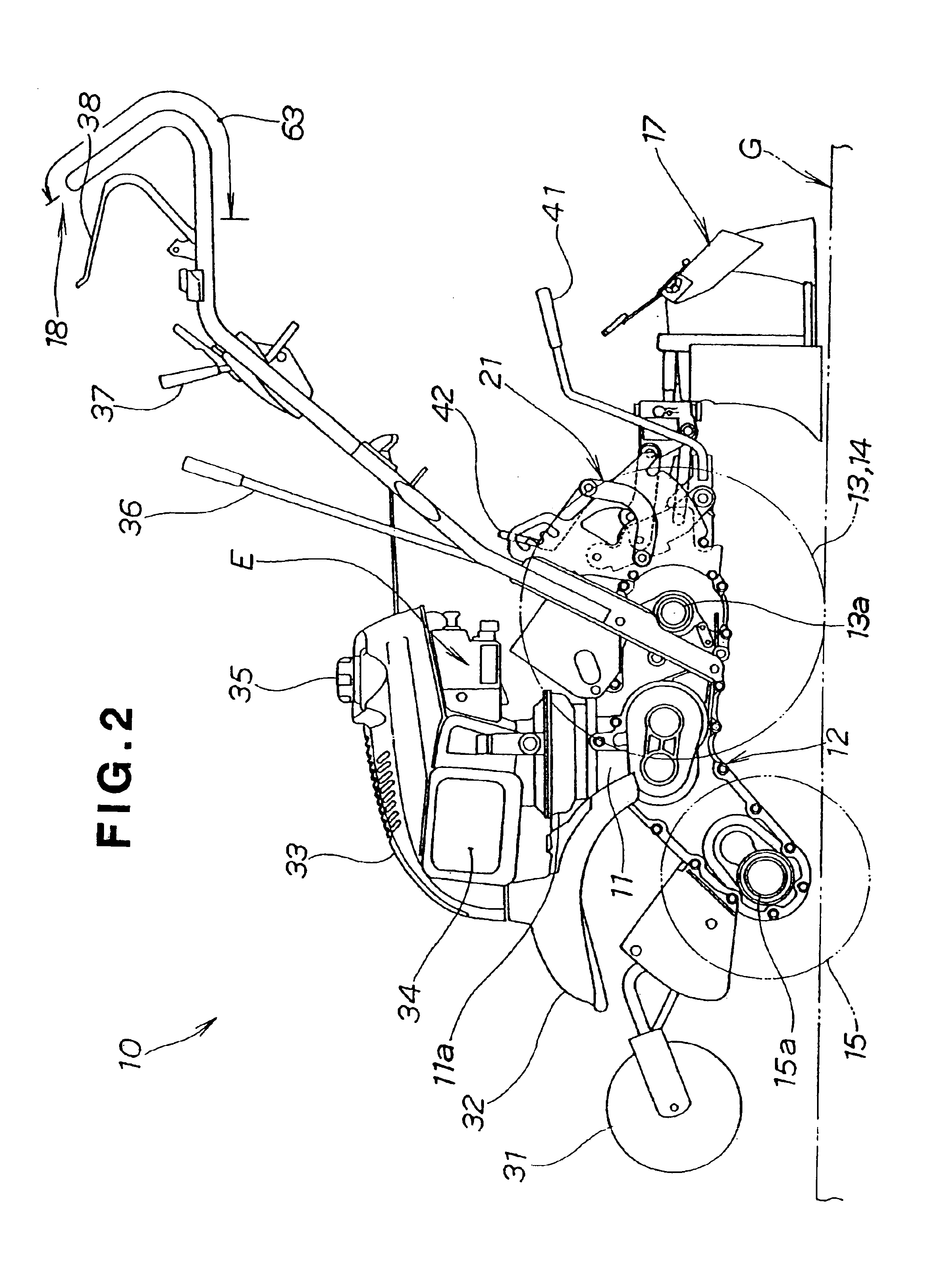
A walk-behind tiller (hereinafter referred to merely as a “tiller”) 10 according to the present invention shown in FIGS. 1 to 3 includes a body 11, an engine E provided on the body 11, a power transmission 12 mounted to the body 11, left and right travel wheels 13, a tilling device 15, and an operating machine such as a ridger 17 provided behind the travel wheels 13, for tilling agricultural field with the tilling device 15 while furrowing. The power transmission 12 transmits power generated by driving of the engine E to the left and right travel wheels 13 and to the tilling device 15.

As shown in FIG. 2, the power transmission 12 is mounted below a clutch case 11a containing a clutch provided below the engine E. The tilling device 15 is rotatably mounted to the front of the power transmission 12 via a rotor shaft 15a. The left and right travel wheels 13 are rotatably mounted to the rear of the power transmission 12 via an axle 13a. A handle 18 obliquely extends from the rear of the ...


PUM


Abstract

A walk-behind tiller has a body and a pair of wheels mounted on the body for undergoing rotation to cause the walk-behind tiller to undergo travelling along a ground surface. A tilling device is mounted on the body for undergoing a first movement operation in which the tilling device travels along the ground surface while the tilling device is disposed in spaced-apart relation to the ground surface, a second movement operation in which the tilling device tills the ground, and a third movement operation in which the tilling device is maintained generally horizontal to the ground surface. A handle has proximal portions, a pair of grip portions connected to the proximal portions and configured to be gripped by an operator to maintain the tilling device generally parallel to the ground surface during the third movement operation, a pair of rising portions connected to the grip portions and configured to be tilted by the operator during the second movement operation to cause the tilling device to till the ground, and a cross portion disposed between the rising portions and configured to be gripped and pressed by an operator to produce a force tending to move the tilling device about the rotational axis to maintain the tilling device in spaced-apart relation to the ground surface.

Description

FIELD OF THE INVENTIONThe present invention relates to a walk-behind tiller and, more particularly, to an improved loop-shaped handle extending obliquely from the rear of a tiller body rearwardly upwardly.BACKGROUND OF THE INVENTIONThis kind of loop-shaped handle is disclosed, for example, in Japanese Utility Model Laid-Open Publication No. SHO-63-44310. This handle has a vertical position adjusting structure so that the handle is vertically adjustable to a height. This handle structure will be described with reference to FIGS. 14 and 15 hereof.Referring to FIGS. 14 and 15, the handle 100 is loop-shaped handle and has a pair of left and right handle bars 102, 102 obliquely extending rearwardly upwardly from a handle mounting portion 120 provided at the rear of a tiller body (not shown), and a linear horizontal handle bar 103 extending transversely of the body for connecting the rear ends of the handle bars 102, 102.A C-shaped member 104 protruding toward the tiller body is mounted t...

Claims


Application Information

Patent Timeline
Patent Type & Authority Patents(United States)
IPC IPC(8): A01B33/02A01B33/00B62D51/00B62D51/06A01B69/00
CPCA01B33/028B62D51/06Y10T16/513Y10T16/499A01B69/00
Inventor YAMAZAKI, NOBUOIINO, KEIJIKANBARA, FUMIYOSHIOOTA, YOSHITAKA
Owner HONDA MOTOR CO LTD
Why Eureka
Try Eureka