
Wheelchair drive unit

a drive unit and drive shaft technology, applied in the field of wheelchair drive units, can solve the problems achieve the effects of limiting the extent to which the struts can open and the force the struts can impose on the frame, shortening the length of the lifting strap, and limiting the struts' ability to li

Inactive Publication Date: 2005-03-01
DAKA RESEARCH INC
View PDF24 Cites 46 Cited by
  • Summary
  • Abstract
  • Description
  • Claims
  • Application Information

AI Technical Summary

Benefits of technology

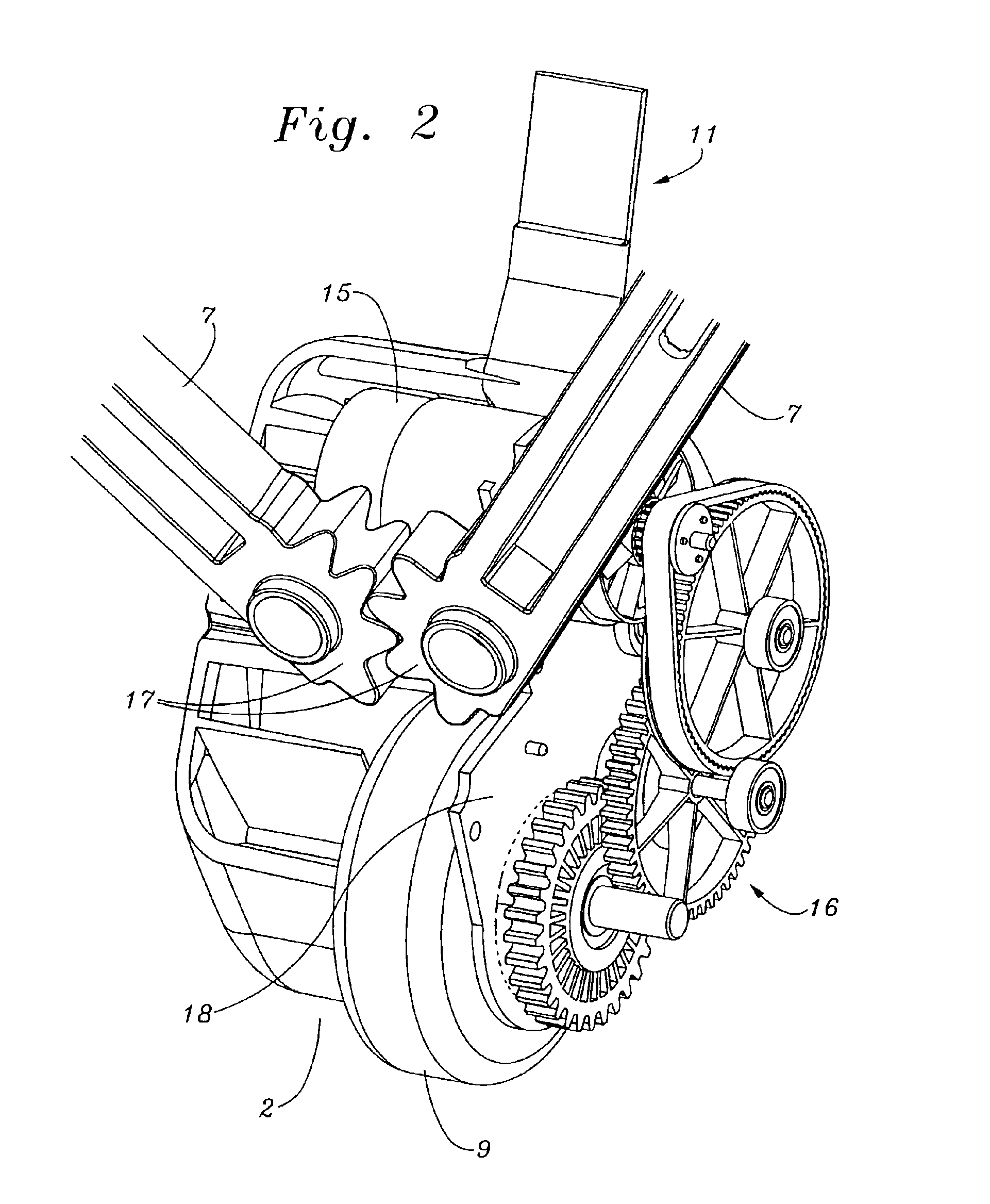
According to the present invention there is provided an electric drive attachment for a wheelchair comprising a drive housing containing an electric motor, a drive wheel which touches the ground and drives the wheelchair through frictional contact with the ground and speed reducing mechanism between the motor and drive wheel, attachment structure to attach the wheelchair drive unit to the wheelchair, said attachment structure preferably being a pair of clamps one on each side of the frame, each clamp containing a pivoting hinge which can be withdrawn from the clamp by aligning a tang on the pivot with a groove in the clamp, the axis of the hinge being parallel to the axis of the wheelchair rear wheels, two connecting struts of adjustable length fitted between the pivoting hinges and the drive housing, said connecting structure being in the shape of a ‘V’ so that the drive housing sits centrally between the two clamps and is free to pivot at the clamps on the aforementioned axis and each end of the struts able to pivot in the plane of the ‘V’ so that the ‘V’ can open and close and with the ends of the struts at the drive housing incorporating meshing gear teeth so that the struts mesh with each other and therefore open equally about a centerline between them, and such that an angle between the drive wheel ground contact point and the center of the axis of the pivoting hinges, and a vertical line through the center of the pivoting hinges is about 35 degrees, a visible mark on the drive housing that, when vertical, indicates the aforementioned angle is correct. A flexible length adjustable connector that ties the two struts to each other near the clamps thereby limits the extent to which the struts can open and limiting the forces the struts can impose on the frame. A lifting strap of adjustable length is provided which attaches to the drive unit and has a loop at the other end that slips over and is secured by a wheelchair handle. The lifting strap incorporates a shortening device that effectively shortens the length of the lifting strap when activated to thereby raise the drive housing and drive wheel off the ground. The lifting strap also affording a way to quickly raise the drive housing and drive wheel substantially clear of the ground by simply pulling upwards. The lifting strap also acts to stop the drive unit and drive wheel from under running the wheelchair by restricting the degree to which the drive unit can pivot about the pivoting hinges. An optional anti under run roller can also be utilized to further limit the angle which the drive unit can achieve with respect to the ground surface.
Also included are torque dampening systems to reduce the shock of starting the motor, a clutch which enables manual forward movement of a wheelchair without engagement of the motor and without dragging of the drive wheel, an anti under run roller that limits the degree to which the wheelchair drive unit can under run the wheelchair and positive pressurization of the gear works and area surrounding the drive wheel to keep the housing free of debris.

Problems solved by technology

A flexible length adjustable connector that ties the two struts to each other near the clamps thereby limits the extent to which the struts can open and limiting the forces the struts can impose on the frame.

Method used


Image

  • Wheelchair drive unit
  • Wheelchair drive unit
  • Wheelchair drive unit

Examples


Embodiment Construction

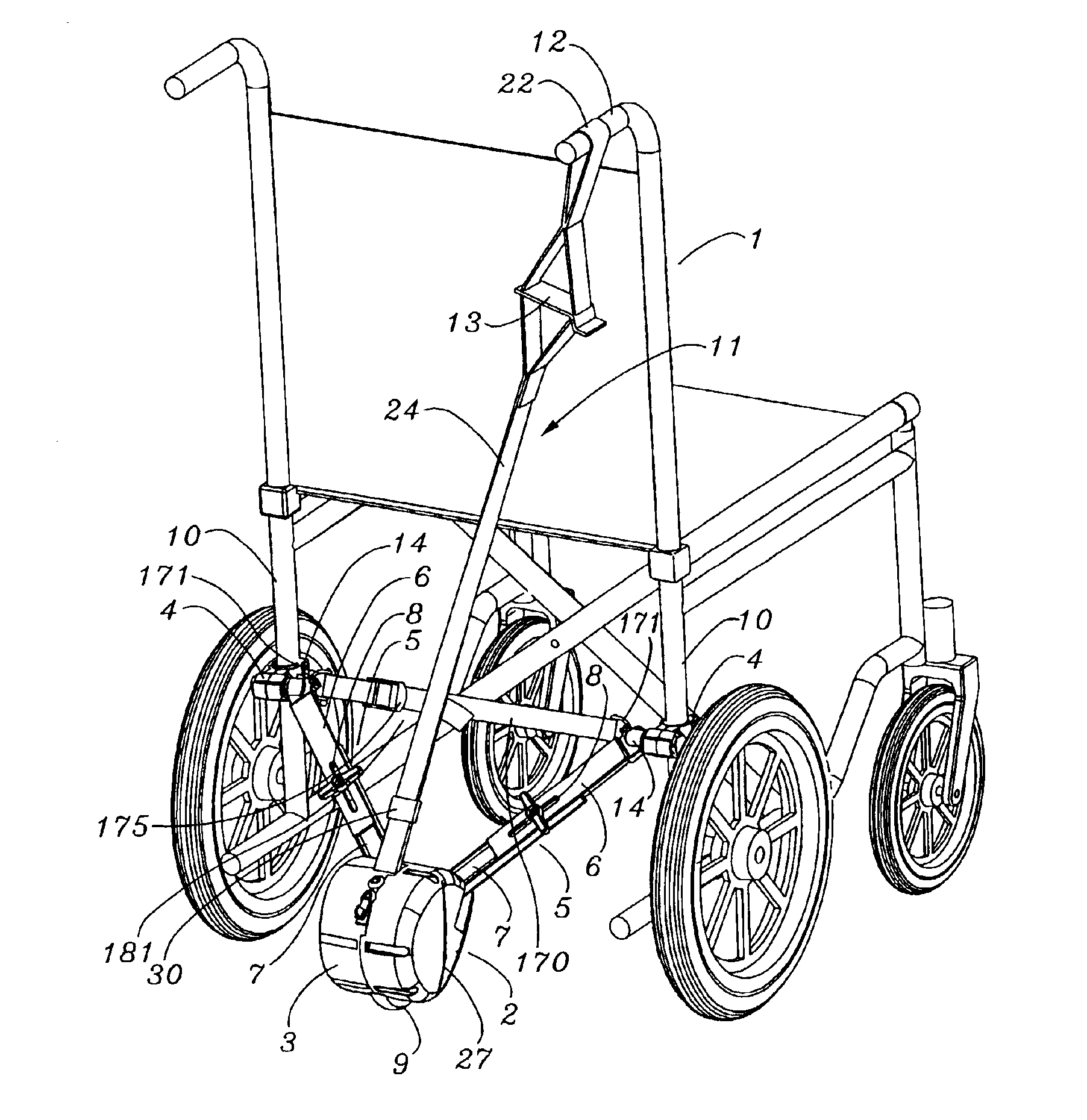
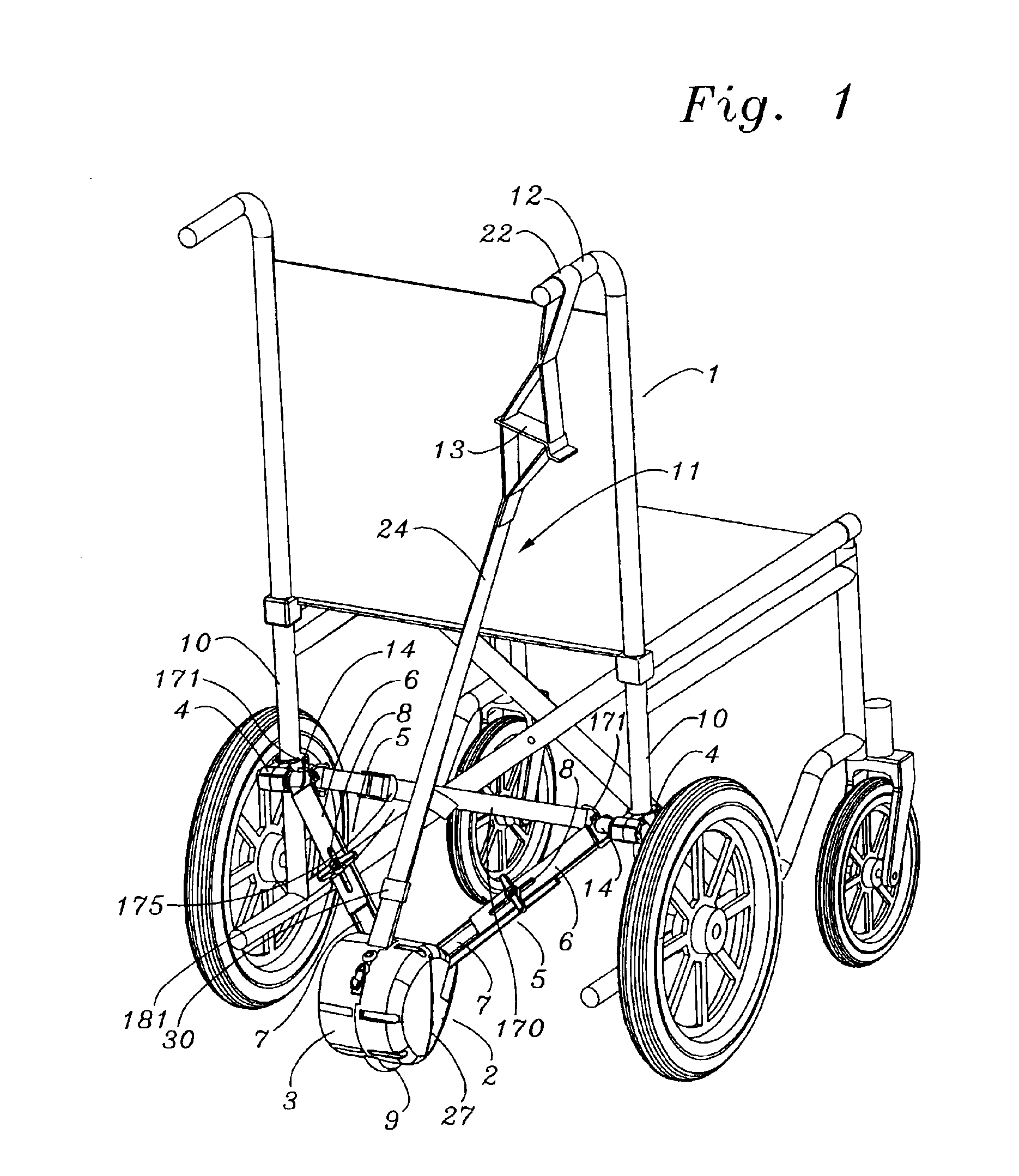
Referring to FIG. 1, a wheelchair 1 is shown as having an attached wheelchair drive unit 2 having an outer drive housing 3, attachment clamps 4, and adjustable struts 5 which position the drive unit 2 at the center of the wheelchair 1. Wheelchair 1 is of the small wheel type where the rear wheel has a smaller diameter and an axis of pivot mounted lower with respect to the chair occupant.

Adjustable struts 5 are each assembled from a clamp half strut 6 and a drive housing half strut 7. The length of each strut 5 can be locked off via wing nut 8 and a bolt (not shown). Drive wheel 9 is seen at the bottom of drive unit 2. Also note, as is seen in a numbering sequenced for FIG. 10, a tie strap 170 is seen as being connected to each clamp half strut 6 near the clamp 4 via connecting shackles 171. An adjuster 175 allows the tie strap 170 to be shortened or lengthened to suit different wheelchair 1 sizes and may limit the extent to which struts 5 can open.

Wheelchair 1 is seen as having near...


PUM


Abstract

An electric drive attachment for a wheelchair comprising a drive housing containing an electric motor, a drive wheel which touches the ground and drives the wheelchair through frictional contact with the ground and speed reducing mechanism between the motor and drive wheel, attachment structure to attach the wheelchair drive unit to the wheelchair as a pair of clamps one on each side of the frame. Also included are torque dampening systems to reduce the shock of starting the motor, a clutch which enables manual forward movement of a wheelchair without engagement of the motor and without dragging of the drive wheel, an under run wheel and positive pressurization of the gear works and area surrounding the drive wheel to keep the housing free of debris.

Description

FIELD OF THE INVENTIONThis invention relates to an improved electric drive attachment for a conventional wheelchair.BACKGROUND OF THE INVENTIONWheelchair drive units are well known accessories and fall into two distinct categories. The first category is mounted on the wheelchair and drives the tire of one or more wheelchair wheels. The second category, into which the present invention falls, is attached to the wheelchair and has one or more independent drive wheels which rest on and drive against the ground.It is the action of the drive wheels on the ground which can cause the user problems when they need to negotiate kets or pot holes. While it is known to raise the drive wheel off the ground surface by the use of a cable and lever or screw jack arrangement, these structures and methods are difficult to use or result in minimal ground clearance when actuated.SUMMARY OF THE INVENTIONAccording to the present invention there is provided an electric drive attachment for a wheelchair co...

Claims


Application Information

Patent Timeline
IPC IPC(8): A61G5/04A61G5/00A61G5/08
CPCA61G5/047A61G2203/46A61G2005/0825A61G5/0825
Inventor SINCLAIR, CLIVE MARLESKALOGROULIS, ALEXANDER JOSEPH
Owner DAKA RESEARCH INC
Learn More