Decentralized drive system for a conveyor

a drive system and conveyor technology, applied in conveyor parts, roller-ways, transportation and packaging, etc., can solve the problems of increasing the maintenance needs affecting the reliability of the conveyor system, and high maintenance costs of the spring wrap clutch, so as to avoid noise, power loss and dust.

Inactive Publication Date: 2005-03-01
HYTROL CONVEYOR
View PDF8 Cites 38 Cited by
  • Summary
  • Abstract
  • Description
  • Claims
  • Application Information

AI Technical Summary

Benefits of technology

The present invention addresses the above needs and achieves other advantages by providing an accumulation conveyor system for supporting and moving a plurality of objects. The conveyor system is divided into a plurality of zones wherein each zone includes a top and bottom conveying surface and wherein a space is defined between the top and bottom surfaces. Each zone also includes its own motor positioned external to the space between the conveying surfaces and coupled to the conveying surfaces via a non-slip connection. The non-slip connection avoids the noise, power loss and dust generated by clutch conveyor systems. A control system is connected to the motor and controls the motor speed (such as by controlling the frequency of power supplied to the motor) so that the conveying surfaces in each zone can be moved independently. Whenever a sensor detects an empty downstream zone, it signals the upstream zone of the control system to power the motor and move the object to fill the empty zone. The control system may also be configured to allow a soft start wherein motor power is increased gradually so as to avoid the impact that occurs with low-slip clutches.

Problems solved by technology

Such chain drive systems involve the use of many moving parts which generally decreases reliability and increases maintenance needs of the conveyor system.
Spring wrap clutches are high-maintenance item, particularly over extended periods of use.
Also, spring wrap clutches make noise when engaging and disengaging, and a large number of clutches combined with the noise of the other parts of the chain drive system result in a noisy conveyor system that is unpleasant for workers.
An alternative to the spring wrap clutch is a pneumatic clutch, but pneumatic clutches are usually expensive and require a supply of compressed air to operate.
Clutches also have the problem of causing a “hard start” wherein low-slip clutches engage suddenly, and present a jarring impact to the drive system.

Method used


Image

  • Decentralized drive system for a conveyor
  • Decentralized drive system for a conveyor
  • Decentralized drive system for a conveyor

Examples


Embodiment Construction

The present inventions now will be described more fully hereinafter with reference to the accompanying drawings, in which some, but not all embodiments of the invention are shown. Indeed, these inventions may be embodied in many different forms and should not be construed as limited to the embodiments set forth herein; rather, these embodiments are provided so that this disclosure will satisfy applicable legal requirements. Like numbers refer to like elements throughout.

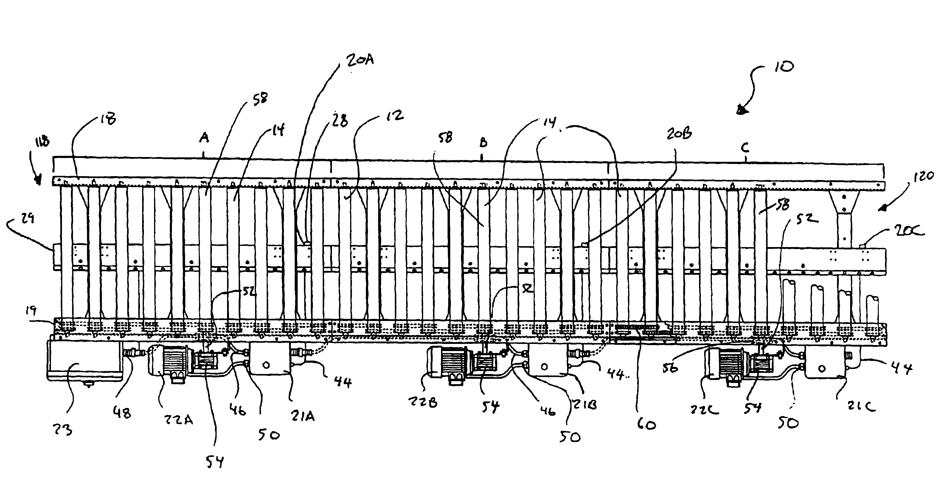
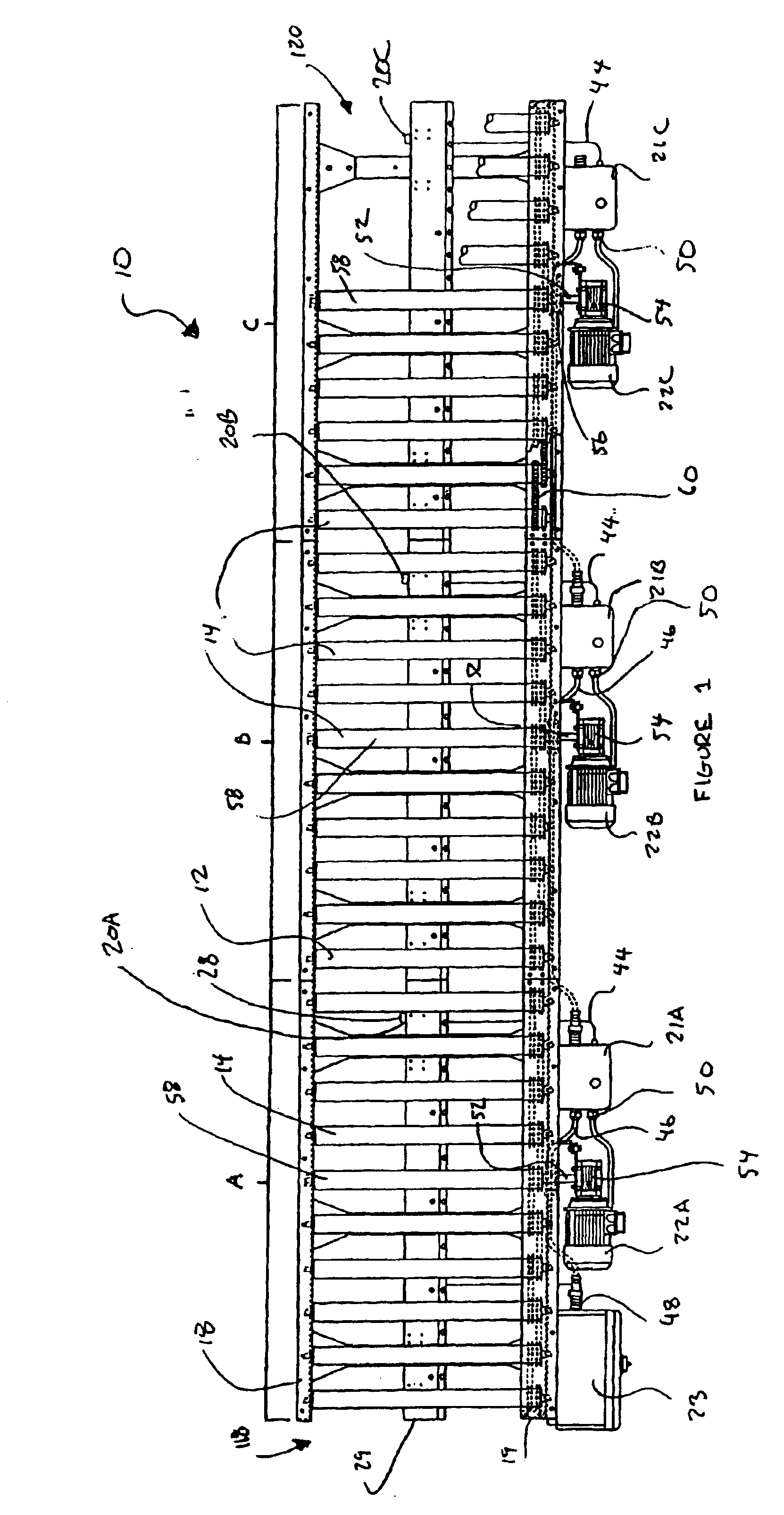
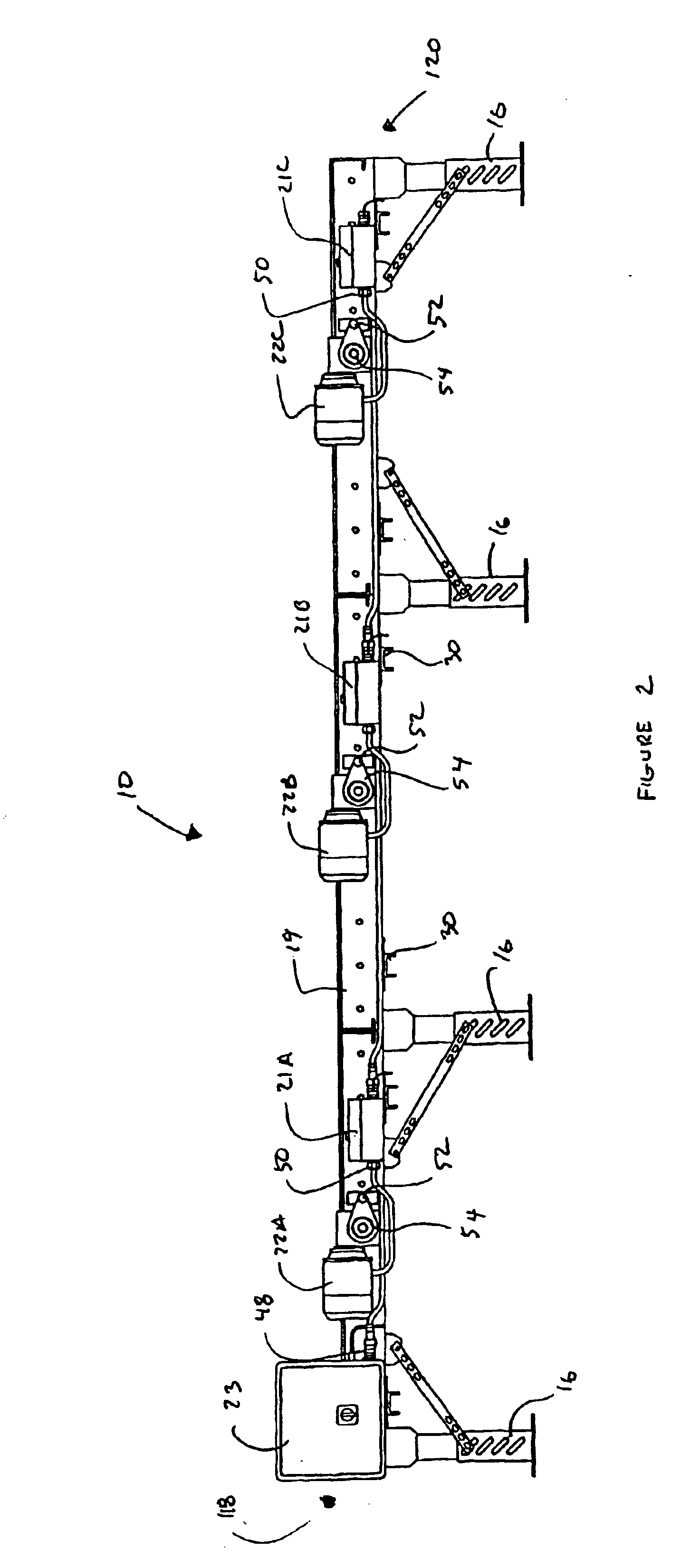
A zero-pressure accumulation conveyor 10 includes an upper (top) conveying surface 12 and a lower (bottom) surface 13 defined, in this case, by the tops and bottoms, respectively, of a plurality of rollers 14, as shown in FIG. 7. It should be noted, however, that other types of conveying surfaces, such as belts, slats, or modular plastic belts may be used. In the case of one type of belt conveying surface the upper portion of the belt is the conveying surface that supports objects being conveyed thereon and defines t...


PUM


Abstract

An accumulation conveyor system for supporting and moving a plurality of objects. The conveyor system is divided into a plurality of zones wherein each zone includes a top and bottom conveying surface and wherein a space is defined between the top and bottom surfaces. Each zone also includes its own motor positioned external to the space between the conveying surfaces and coupled to the conveying surfaces via a non-slip connection. A control system is connected to the motor and controls the power to the motor so that the conveying surfaces in each zone can be moved independently. Whenever a sensor detects an empty downstream zone, it signals the control system of the upstream zone to power the motor and move the object to fill the empty zone. The control system may also be configured to allow a soft start wherein motor speed is increased gradually.

Description

BACKGROUND OF THE INVENTION1. Field of the InventionThe present invention is directed to conveyor systems, and more particularly to drive assemblies for accumulation conveyor systems.2. Description of Related ArtConveyors are used to transport goods and packages in all types of environments and experience especially heavy use in manufacturing and shipping industries. In addition, characteristics of the flow of goods and packages along such conveyor systems, such as timing and positioning of the goods and packages, must often be tailored to the needs of the manufacturer or shipper. Accumulator conveyor systems are divided into zones in which a driving force may be selectively applied to a conveying surface which provides each package with a stopping position. As a result, packages or goods may be accumulated in successive zones for eventual discharge from the conveyor.As an example, U.S. Pat. No. 5,862,907 to Taylor (“Taylor”) discloses an accumulation conveyor 10 that is divided int...

Claims


Application Information

Patent Timeline
Patent Type & Authority Patents(United States)
IPC IPC(8): B65G43/10B65G47/26
CPCB65G47/261B65G43/10
Inventor NEWSOM, GREGORY SCOTTSUPINE, ANTHONY JOHNWALLACE, PAUL DEWAYNEBONHAM, BOYCE DEAN
Owner HYTROL CONVEYOR
Why Eureka
Try Eureka