
Deployable projectiles

a projectile and projectile technology, applied in the field of projectiles, can solve the problems of lack of effective measures against weapons such as shoulder-fired rpg weapons, no such weapons have been planned nor are in development, and achieve the effects of effective defeating, high effective protection, and incremental enhancement of effectiveness and performan

Inactive Publication Date: 2005-03-01
OMNITEK PARTNERS LLC
View PDF8 Cites 7 Cited by
  • Summary
  • Abstract
  • Description
  • Claims
  • Application Information

AI Technical Summary

Benefits of technology

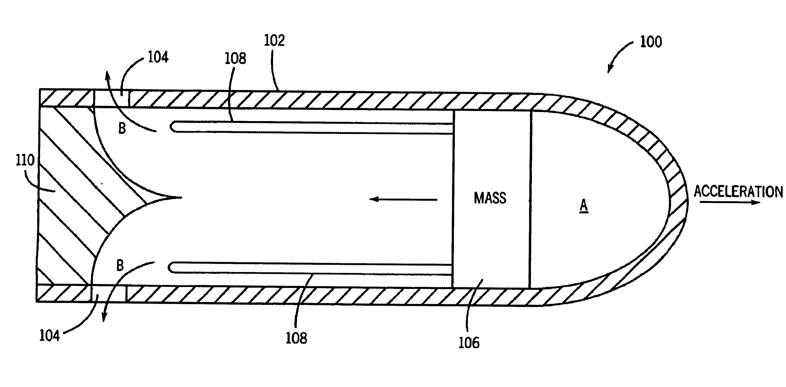
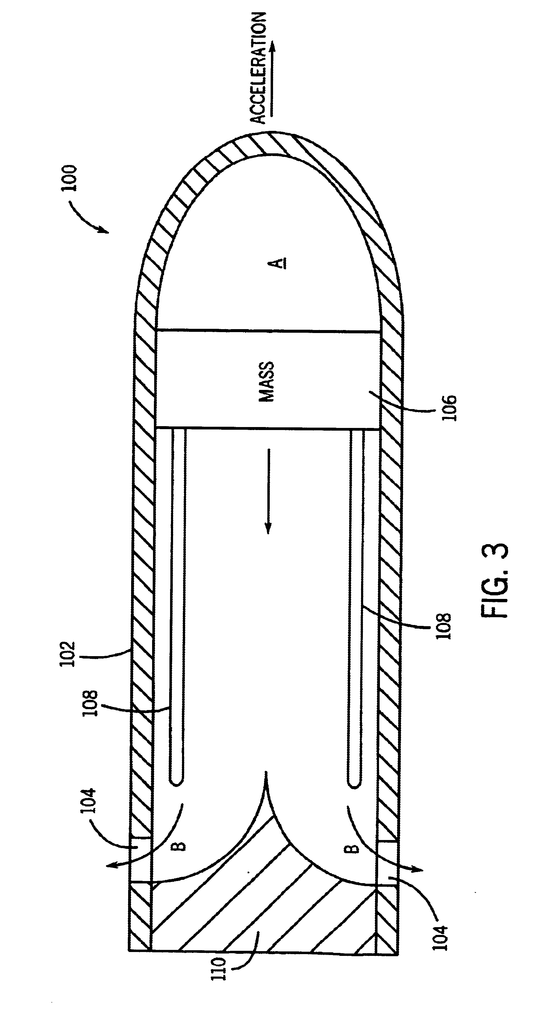
The present invention provides novel projectiles that can effectively defeat shoulder fired rockets or the like within a radius of 50 meters. The projectiles are designed to be highly effective protective weapons and can be used in various modes of application. They can be used as a supplement to existing anti-missile protection systems or as the last protective weapon if all other weapons fail. The projectiles have the advantage of being highly passive and not requiring any sophisticated electronics or sensory gear. They can be guided and controlled using on-board sensors and decision-making components. The projectiles can be fired from a regular gun and can deploy a propeller-like interceptor rotating at high speeds. The method of protecting a second location against a first projectile fired from a first location at the second location involves firing at least one second projectile toward the first projectile and deploying one or more projections from the second projectile to increase its footprint and probability of destroying or changing the trajectory of the first projectile. The interceptor projectile can be guided and directed using a curved portion disposed in the shell. The invention provides a highly effective protective weapon against shoulder fired rockets or the like.

Problems solved by technology

A review of the existing protective systems clearly indicate the lack of any effective measures against weapons such as shoulder fired RPG type of weapons, particularly those fired at very close range, such as from a 50 meter radius.
No such weapons have been planned nor are under development.

Method used


Image

  • Deployable projectiles
  • Deployable projectiles
  • Deployable projectiles

Examples


Embodiment Construction

The novel intercepting projectiles (alternatively referred to herein as “interceptors”) and their means of delivery for effectively defeating shoulder fired rockets or other similar weapons that are fired from very close range, in the order of a 50 meters radius, will now be described in detail. The basic operation of the systems and methods of the present invention for target interception and target defeat will then be described.

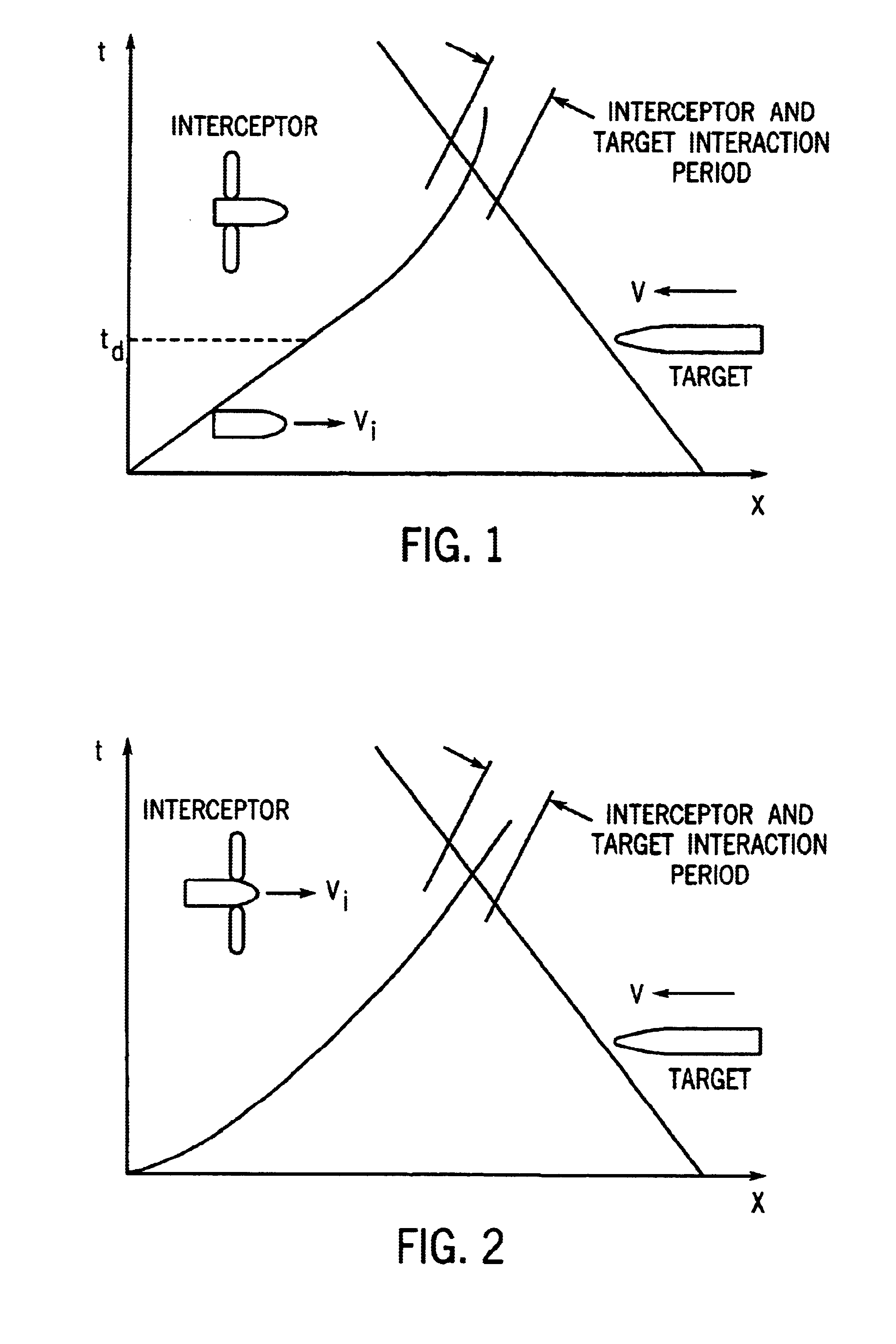
Consider an incoming projectile or missile (target) with a cross-sectional area A (radius r) that is traveling at a speed of V. An intercepting projectile is launched that would deflect or destroy (defeat) the target at an interception distance, L, say about 40 meters.

Let the interceptor projectile be traveling at a speed of Vi and a have a cross-sectional area Ai (radius ri). Also let the closest distance from the center of the target to the center of the intercepting projectile be d. In order to maximize the probability of intercept the following observat...


PUM

PropertyMeasurementUnit
radiusaaaaaaaaaa
radiusaaaaaaaaaa
radiusaaaaaaaaaa

Abstract

A method for protecting a second location against a first projectile fired from a first location at the second location. The method includes: firing at least one second projectile toward the first projectile; and deploying one or more projections from the second projectile to increase its footprint and increase the probability of destroying or changing the trajectory of the first projectile.

Description

BACKGROUND OF THE INVENTION1. Field of the InventionThe present invention relates generally to projectiles, and more particularly, to missiles and other projectiles, which have deployable blades to increase its footprint and / or decrease its momentum.2. Prior ArtNumerous systems have been developed or are under development for protection against various threats such as missiles or projectiles. In certain systems, particularly if weight is not a major problem, a properly designed passive or active armor may provide adequate protection. In other systems, an incoming missile may be defeated by a super-high rate of small to medium caliber fire in either a pure kinetic mode or with the assistance of high explosives. Guided missiles of various kinds have also been developed for such purposes. A number of smart or guided projectiles are also under development for such applications. Many of such protection systems are or planned to be used in combination.A review of the existing protective s...

Claims


Application Information

Patent Timeline
Patent Type & Authority Patents(United States)
IPC IPC(8): F42B10/50F42B12/34F42B10/00F42B12/02F41J2/00F42B10/14F41H11/00F41H11/02H01M2/10H01M2/02H01M12/06H01M12/00H01M10/40H01M10/36
CPCF41H11/02F41J2/00F42B12/34F42B10/50F42B10/14
Inventor RASTEGAR, JAHANGIR S.
Owner OMNITEK PARTNERS LLC
Learn More