Shaft sealing ring

a sealing ring and shaft technology, applied in the field of shaft sealing ring, can solve the problems of reducing service life, early failure, damage to the contact zone of the sealing lip, etc., and achieve the effects of prolonging the service life of the shaft sealing ring, avoiding damage, and being easy to manufactur

Inactive Publication Date: 2005-03-01
DICHTUNGSTECHN G BRUSS
View PDF4 Cites 60 Cited by
  • Summary
  • Abstract
  • Description
  • Claims
  • Application Information

AI Technical Summary

Benefits of technology

to provide a shaft sealing ring including a sealing lip of elastomeric material which will afford effective, reliable, dynamic sealing even at high circumferential speeds and vibrational loading of the shaft, irrespective of the direction of rotation thereof. It is another object of the invention to prolong th

Problems solved by technology

A problem with such shaft sealing rings having a sealing lip of PTFE is that they seal only “dynamically”, in other words, when the shaft is rotating and, what is more, just in one direction of rotation.
Faulty or forgotten mounting of the spring or its popping off while manipulating the shaft sealing ring before or during assembly of the shaft sealing ring is known to cause early failure

Method used


Image

  • Shaft sealing ring
  • Shaft sealing ring

Examples


Embodiment Construction

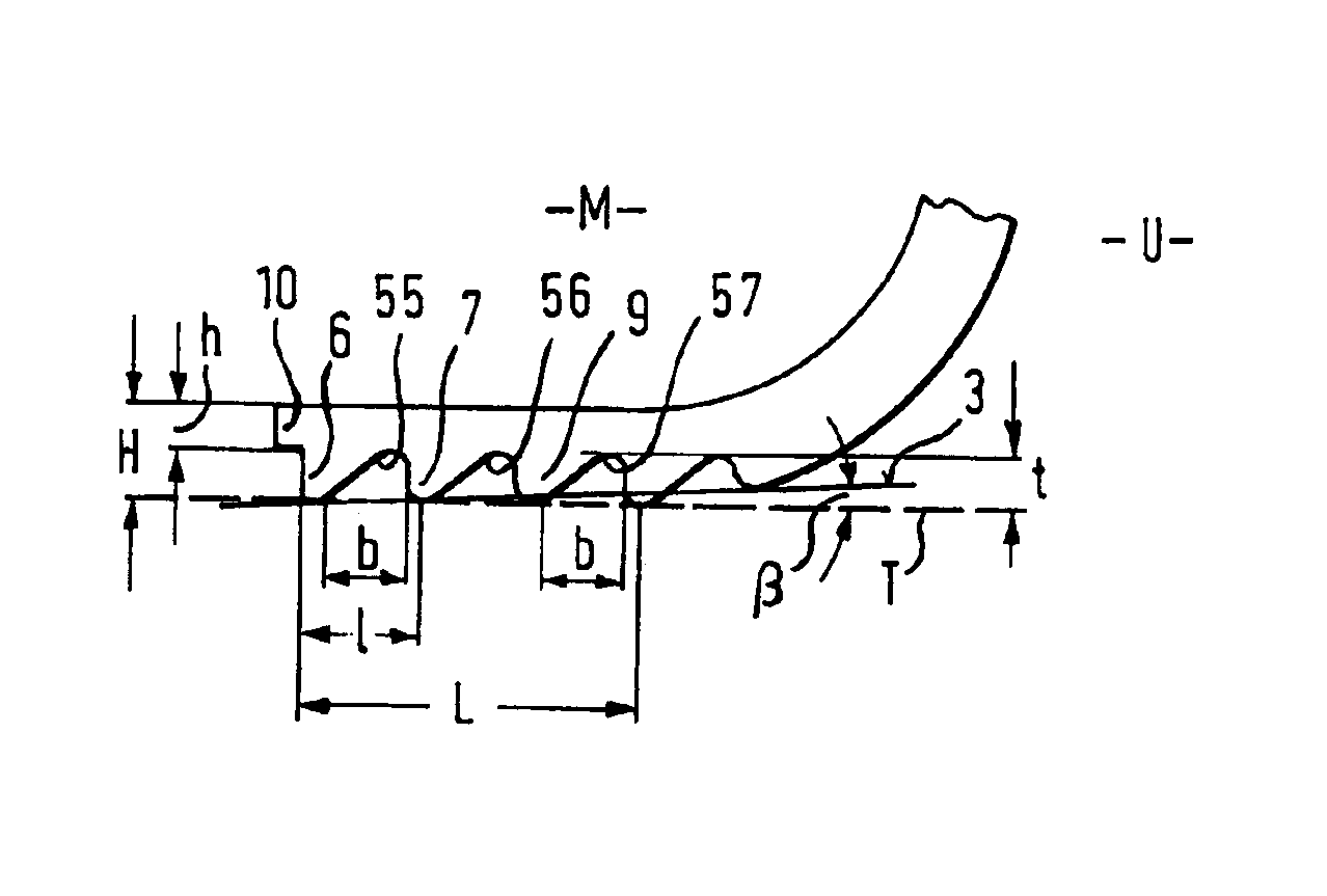
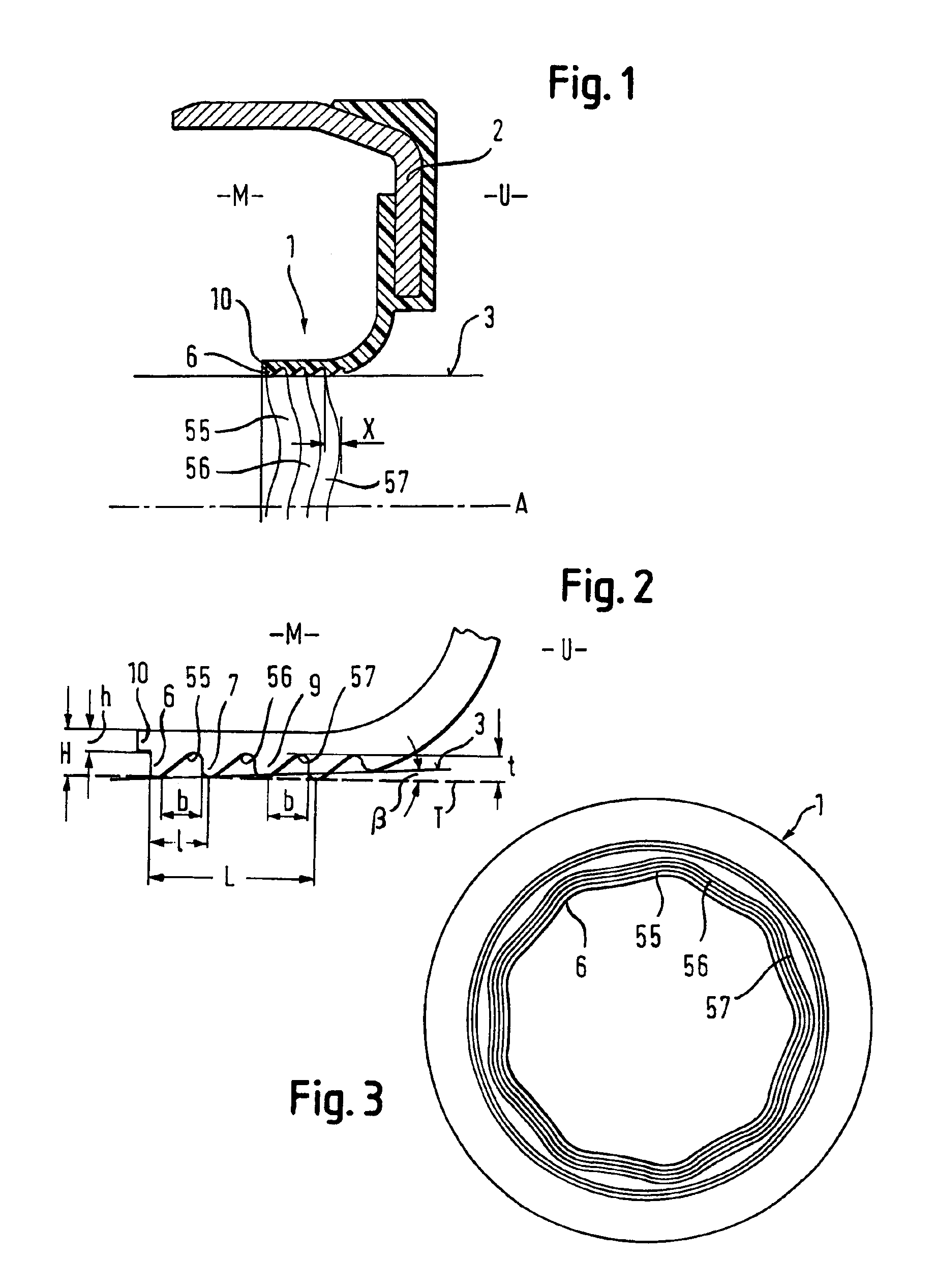
A shaft sealing ring shown in the figures for a shaft whose periphery is designated 3 comprises a sealing sleeve with a sealing lip made of an elastomer and connected directly to a stiffening plate 2 by vulcanizing. By virtue of its dimensioning, the sealing lip is flaccidly bendable, i.e. easily to be bent, and it is not pressed against the periphery 3 of the shaft by a separate spring such as a worm spring as usual.

When not installed, the sealing lip 1 is stretched out radially (cf. FIG. 3) and has an inner diameter which is smaller than the outer diameter of the shaft to be sealed. Once mounted, the sealing lip 1 is curved, as illustrated in FIG. 2, in a direction parallel to the axis of the shaft so that the sealing lip I approaches the shaft tangentially and has a cylindrical portion 11 entering into surface area engagement, along an axial length L, with the periphery of the shaft under slight contact pressure caused alone by the flexural elasticity of the sealing lip 1. The di...


PUM


Abstract

A shaft sealing ring for a shaft comprises a sealing lip made of an elastomeric material or a PTFE compound and dimensioned as to be flaccidly bendable. The flexural elasticity is selected such that it will just be sufficient to press a sealing portion of the sealing lip into sealing engagement with the periphery of the shaft. The sealing portion of the sealing lip engages the periphery for a predetermined length. In the sealing portion, the sealing lip is provided along its circumference, at the side of the shaft, with endless, undulating return channels at least throughout this length. These channels return any medium escaping during rotation of the shaft to the space to be sealed. The return channels do not communicate with the surroundings of the shaft sealing ring. No seperate contact pressure means, such as a helical ring coil spring is required to press the sealing lip into engagement with the shaft.

Description

The instant invention relates to a shaft sealing ring having a sealing lip which is made of an elastomer.BACKGROUNDDuring the past few years shaft sealing rings of elastomeric material often were replaced by shaft sealing rings whose sealing lips were made of polytetrafluoroethylene (PTFE) when intended for sophisticated applications, such as to be used in modem internal combustion engines. It has been suggested with such shaft sealing rings to provide a thread in a sealing portion thereof which will be in engagement with a surface area of the shaft, when the shaft sealing ring is mounted, so as to return the medium to be retained (lubricant) back into the space to be sealed when the shaft rotates (cf. H. K. Mueller “Abdichtung bewegter Maschinenteile”, 1990 Medienverlag Ursula Mueller, pages 42, 43, picture 18-RD).A problem with such shaft sealing rings having a sealing lip of PTFE is that they seal only “dynamically”, in other words, when the shaft is rotating and, what is more, j...

Claims


Application Information

Patent Timeline
IPC IPC(8): A61B5/055F16J15/32G01R33/54F16J15/3228F16J15/3244
CPCA61B5/7475F16J15/3244F16J15/3228
Inventor HACKER, GUNTHERJOHNEN, ROLFSCHMITT, WOLFGANG
Owner DICHTUNGSTECHN G BRUSS
Why Eureka
Try Eureka