Screw member with biting features

a technology of screw member and biting feature, which is applied in the direction of threaded fasteners, screws, fastening means, etc., can solve the problems of reducing the relative strength of the first screw member and the second screw member, and achieve the effect of reliable prevention of loosening

Inactive Publication Date: 2005-03-01
ISHIMORI YUSAKU
View PDF15 Cites 8 Cited by
  • Summary
  • Abstract
  • Description
  • Claims
  • Application Information

AI Technical Summary

Benefits of technology

According to the present invention, since the both crest portions formed on the first screw member bite into the second screw member while cutting the second screw mem

Problems solved by technology

Therefore, there is a problem in that a fastening power and a relative

Method used


Image

  • Screw member with biting features
  • Screw member with biting features
  • Screw member with biting features

Examples


Embodiment Construction

Embodiments of the present invention will now be described, with reference to the drawings.

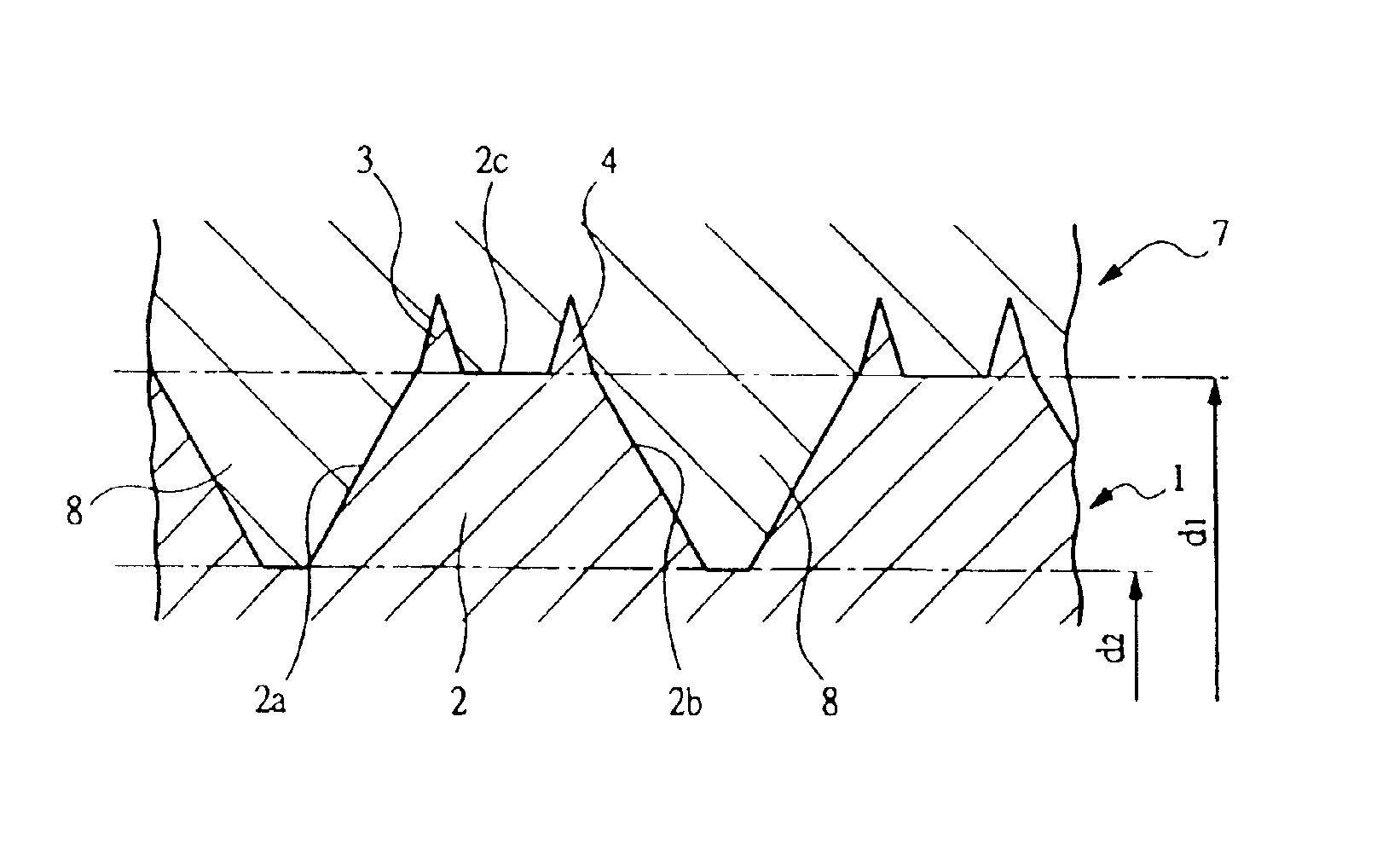
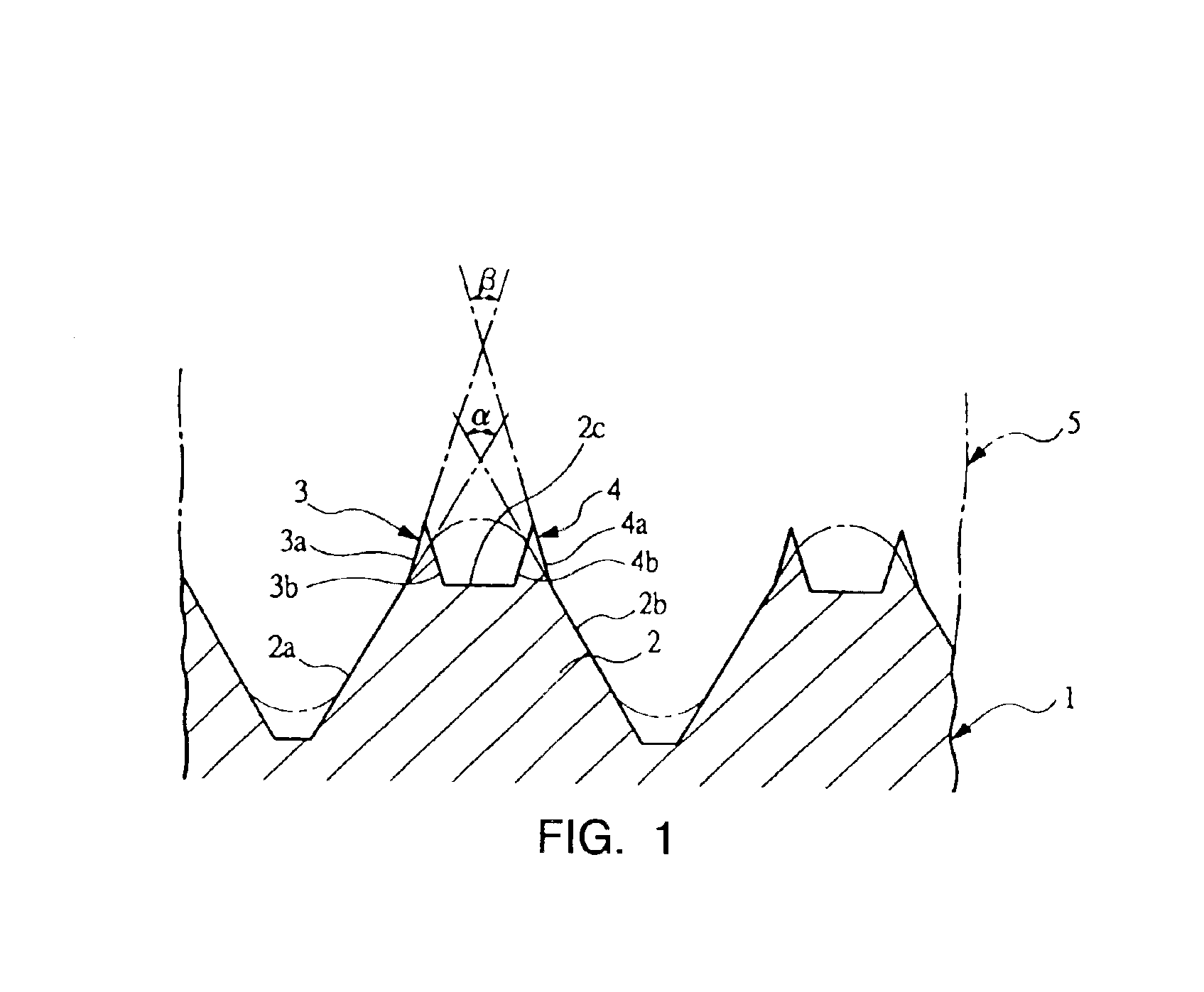
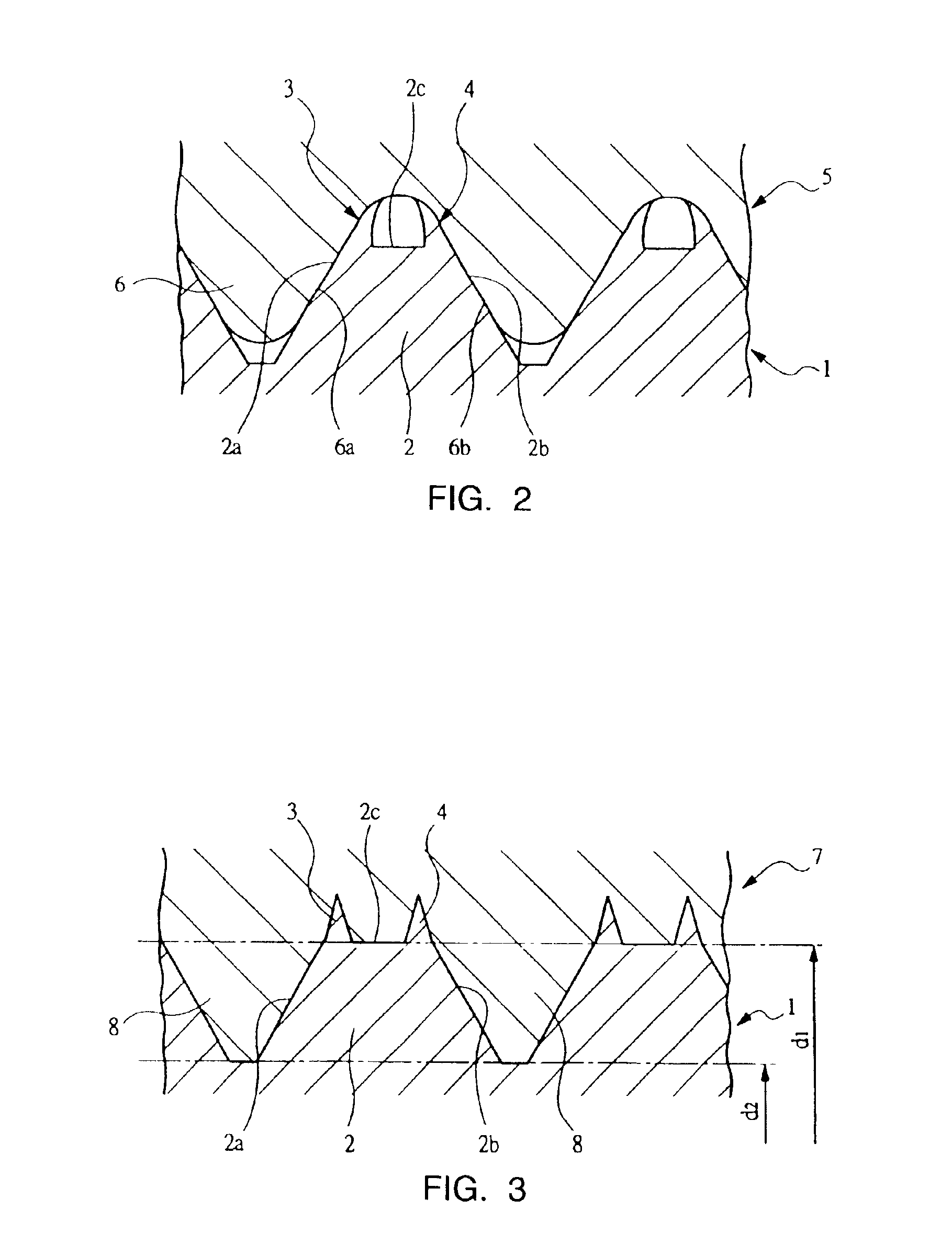
FIG. 1 is a sectional view showing a part of a screw member, which is one embodiment of the present invention. FIG. 2 is a sectional view showing the state in which this screw member is thread-connected with an other screw member. FIG. 3 shows the state in which the screw member shown in FIG. 1 and FIG. 2 is thread-connected to a second screw member in which a screw thread is formed having a screw groove with an inner diameter d1. FIGS. 4A to 4C are sectional views showing a whole screw member.

FIG. 4A shows a screw member comprising a first screw member 1 consisting of a bolt, and a second screw member 5 consisting of a nut. The first screw member 1 has screw threads 2 formed thereon, helically protruding from the circumference of a screw body in a cylinder shape, with a screw groove formed between screw threads. On the other hand, the second screw member 5 has screw threads 6 formed thereon, ...


PUM


Abstract

A screw member having a loosening prevention function is provided to improve a fastening power and a relative strength in thread connection. With an arrangement to provide a first crest portion and a second crest portion at the opposite ends of a thread point, a first screw member generates a loosening prevention effect due to elastic deformation of the first crest portion and the second crest portion, with the entire thread flank from the base portion to the point brought into contact with a second screw member on the both surfaces of the thread flanks. With this arrangement, a strong fastening power can be obtained, and a clamping force applied to the thread is distributed over the thread, thereby enabling improvement in the relative strength in thread connection.

Description

FIELD OF THE INVENTIONThe present invention relates to a screw member for fastening a plurality of members to be fastened, and more particularly, relates to a technique for preventing the fastening of the members from becoming loose.BACKGROUND OF THE INVENTIONIn order to fasten a plurality of members to be fastened, screw members such as bolts and nuts are often used, and in order to prevent the fastened screw members from becoming loose, a locking member such as a spring washer is normally used.In order to prevent the screw members fastened to each other from becoming loose, without using such an additional part, there has been used a self-lock screw member as described in the Japanese Patent Publication No. 56-19492 and the Japanese Patent Publication No. 3-46686.The self-lock screw member described in the Japanese Patent Publication No. 56-19492 is constructed such that a flank angle of a screw thread of a first screw member is set to be smaller than a flank angle of a screw thre...

Claims


Application Information

Patent Timeline
IPC IPC(8): F16B33/00F16B39/30F16B33/02F16B39/00F16B39/284F16B39/02
CPCF16B33/02F16B39/30F16B39/284F16B39/02
Inventor WATANABE, TETSUYA
Owner ISHIMORI YUSAKU
Why Eureka
Try Eureka