Hydrogen supply device

a technology of water supply device and water supply device, which is applied in the direction of electrically induced generators, mechanical apparatus, chemical/physical/physical-chemical processes, etc., can solve the problems of increasing the weight of the device, complex devices, and large devices, and achieve the effect of increasing the speed of heating

Inactive Publication Date: 2005-03-01
HONDA MOTOR CO LTD
View PDF8 Cites 10 Cited by
  • Summary
  • Abstract
  • Description
  • Claims
  • Application Information

AI Technical Summary

Benefits of technology

In this constitution, since damp air containing water has a greater amount of heat than dry air, and the heat exchange between the hydrogen occlusion tank, the hydrogen occluding alloy, and

Problems solved by technology

However, when cooling water is used as the heating medium for the heat exchanger, a cooling water circuit for feeding back the cooling water must be provided between the hydrogen-using appar

Method used


Image

  • Hydrogen supply device
  • Hydrogen supply device
  • Hydrogen supply device

Examples


embodiment 1

A first embodiment of the hydrogen supply device according to the present invention will be explained with reference to FIGS. 1 to 5.

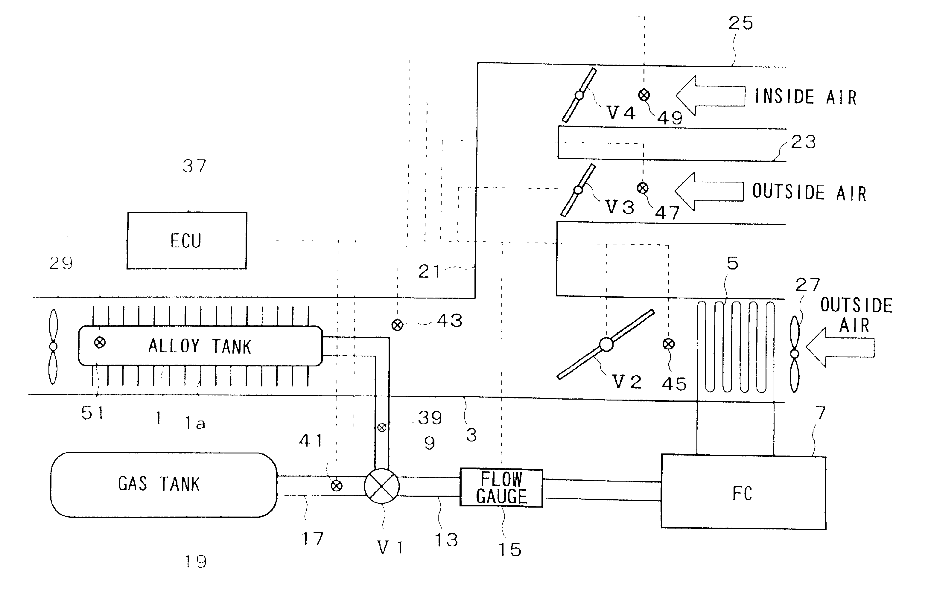
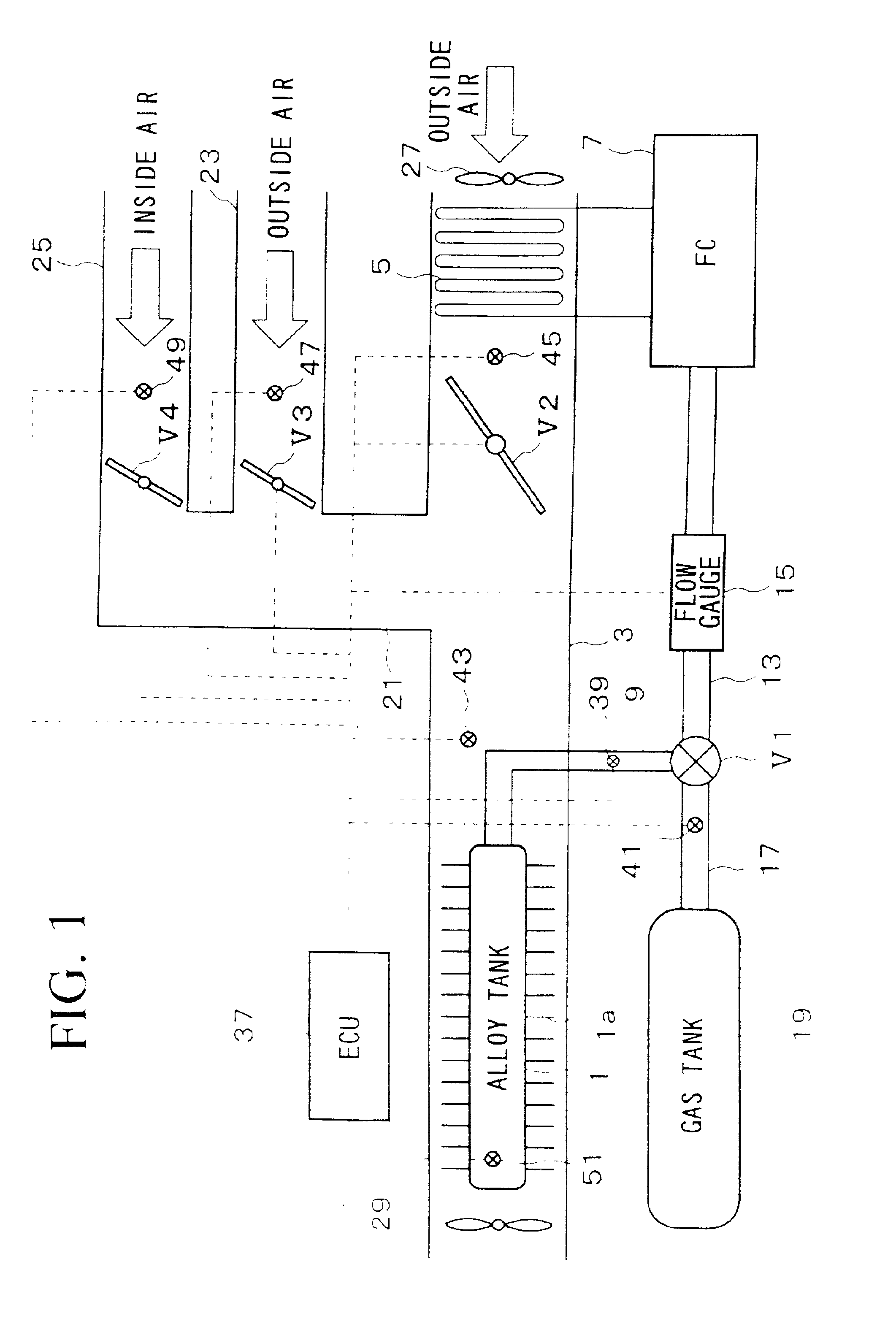
FIG. 1 shows the constitution of a fuel cell system for vehicle comprising a hydrogen supply device. A hydrogen occlusion tank 1 contains a hydrogen occluding alloy, and is provided downstream in a duct (heating unit) 3. The hydrogen occlusion tank 1 comprises stainless steel (SUS304) and is pressure-resistant to 10 MPa. A great number of fins 1a are provided around the outer face of the hydrogen occlusion tank 1. The hydrogen occlusion tank 1 is filled with a hydrogen occluding alloy to a fill rate of 50%. The hydrogen occluding alloy, which is filled in the hydrogen occlusion tank 1, is an LaNi5 alloy having the dissociation pressure characteristics shown by the solid line in FIG. 4, and has dissociation pressure of more than 10 atmospheric pressure at 40 degrees C.

A heat exchange tube (heating unit) 5 is provided inside the duct 3 upstream from the ...

embodiment 2

Subsequently, a second embodiment of the hydrogen supply device according to the present invention will be explained based on FIG. 6. The hydrogen supply device of the second embodiment differs from that of the first embodiment in respect of the source of the heating air which is supplied to the duct 3. This will be explained.

The fuel cell 7 comprises an anode and a cathode on both sides of a solid high-polymer electrolytic film; hydrogen (reaction gas) is supplied to the anode, and air (reaction gas), containing oxygen, is supplied to the cathode, the electrochemical reaction via the solid high-polymer electrolytic film generating electrical energy. In the fuel cell 7, the chemical reaction of hydrogen and oxygen produces water, which vaporizes and is exhausted with the air from the fuel cell 7 as exhaust air (hereinafter “off gas”). Since the chemical reaction also generates heat, the off gas is exhausted at a rather high temperature (e.g. 60 to 80 degrees C.). In the second embod...


PUM

PropertyMeasurementUnit
Temperatureaaaaaaaaaa
Perimeteraaaaaaaaaa

Abstract

The present invention is to provide a hydrogen supply device having a simple constitution which can be made small and light. In the present invention, a hydrogen occlusion tank is provided in a duct. A heat exchange tube is provided upstream from the hydrogen occlusion tank inside the duct. A first fan leads outside air into the duct, and cooling water, which has cooled a fuel cell, is led into the heat exchange tube. A hydrogen occluding alloy is accommodated in the hydrogen occlusion tank, and hydrogen released from the hydrogen occluding alloy is supplied via hydrogen supply pipes and a flow control valve to the fuel cell. Outside air passes through the heat exchange tube and is thereby heated; the heated outside air passes around the perimeter of the hydrogen occlusion tank, thereby heating the hydrogen occlusion tank.

Description

BACKGROUND OF THE INVENTION1. Field of the InventionThe present invention relates to a hydrogen supply device which supplies hydrogen, occluded in a hydrogen occluding alloy, to an apparatus which uses hydrogen, such as a fuel cell or a hydrogen engine.2. Description of the Related ArtA great number of conventional systems have been developed for releasing hydrogen from a hydrogen occluding alloy, which hydrogen is occluded in, and supplying the hydrogen to a hydrogen-using apparatus, such as a fuel cell mounted in a moving body, such as a vehicle (e.g. Japanese Unexamined Patent Application, First Publications Nos. Sho 61-220009 and Hei 1-216024).In the hydrogen occluding alloy, the input and output of heat accompanies the occlusion and release of hydrogen; when occluding the hydrogen, the heat must be discharged from the hydrogen occluding alloy; when releasing the hydrogen, heat must be supplied to the hydrogen occluding alloy. The amount of heat at this time is enormous, being 2...

Claims


Application Information

Patent Timeline
IPC IPC(8): H01M8/06H01M8/04F17C11/00C01B3/00C22C38/40
CPCC22C38/40H01M8/065H01M8/04029Y02E60/50Y02E60/321Y02E60/327Y02E60/32
Inventor SHIMADA, TOSHIAKINUIYA, YOSHIO
Owner HONDA MOTOR CO LTD
Why Eureka
Try Eureka