Air gap interconnect method

a gap interconnect and air gap technology, applied in the direction of instruments, fluid speed measurement, microstructural devices, etc., can solve the problems of poor strength, low fracture toughness, inferior mechanical properties,

Inactive Publication Date: 2005-03-01
INTEL CORP
View PDF5 Cites 250 Cited by
  • Summary
  • Abstract
  • Description
  • Claims
  • Application Information

AI Technical Summary

Problems solved by technology

Although such materials may serve to lower the dielectric constant, they may offer inferior mechanical properties such as poor strength and low fracture toughness.
One major issue facing air gap technology is how to remove sacrificial material to facilitate multi-layer structures.
An

Method used


Image

  • Air gap interconnect method
  • Air gap interconnect method
  • Air gap interconnect method

Examples


Embodiment Construction

In the following detailed description of embodiments of the invention, reference is made to the accompanying drawings in which like references indicate similar elements. The illustrative embodiments described herein are disclosed in sufficient detail to enable those skilled in the art to practice the invention. The following detailed description is therefore not to be taken in a limiting sense, and the scope of the invention is defined only by the appended claims.

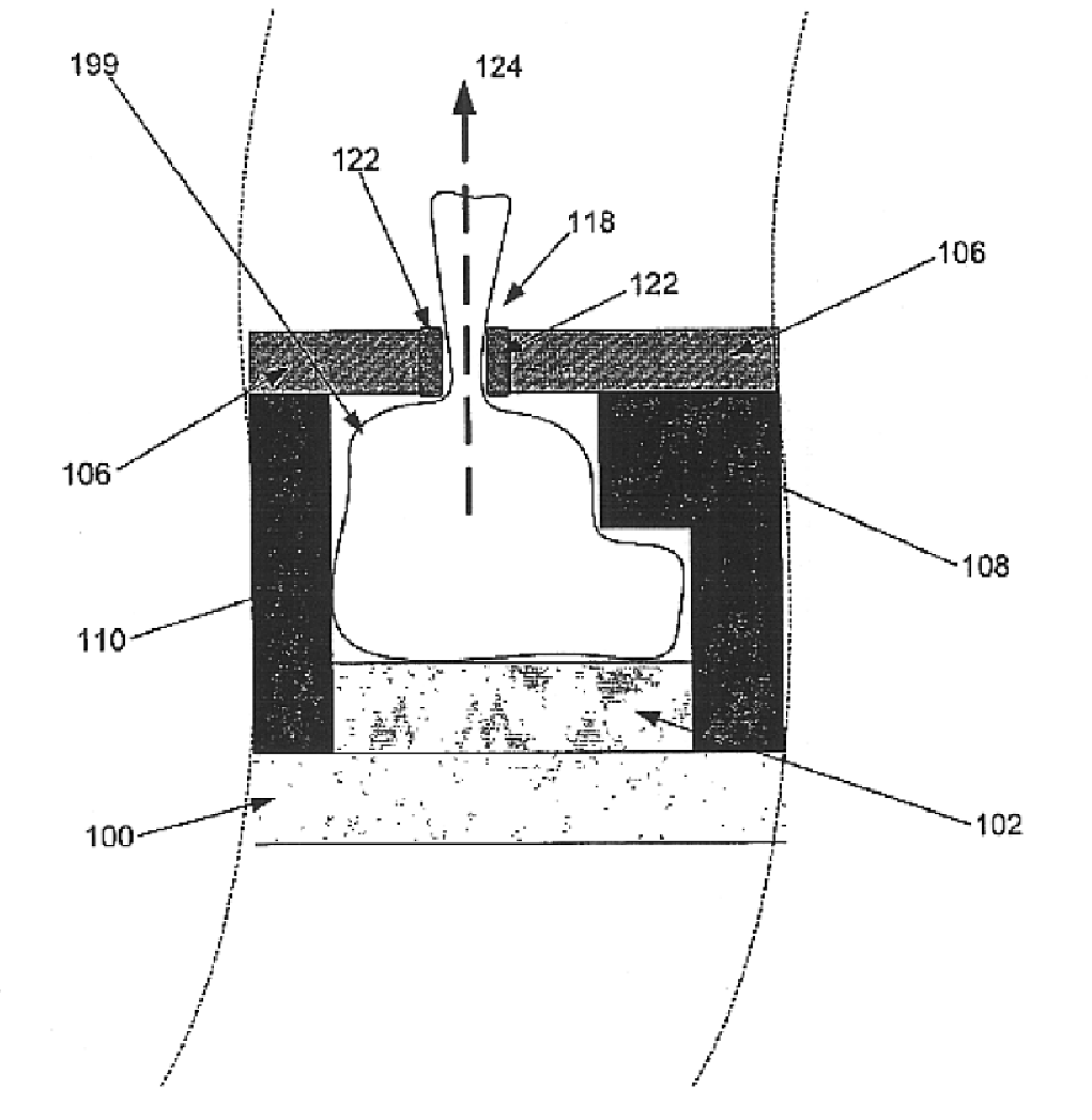
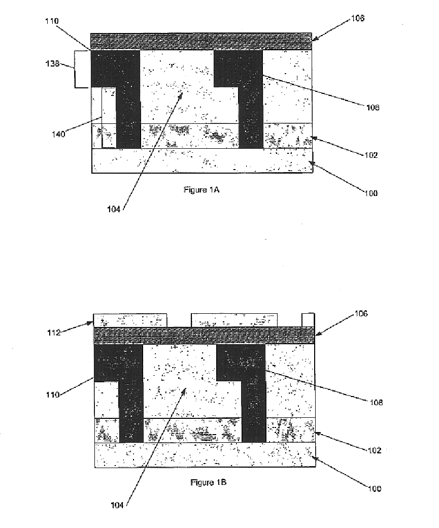
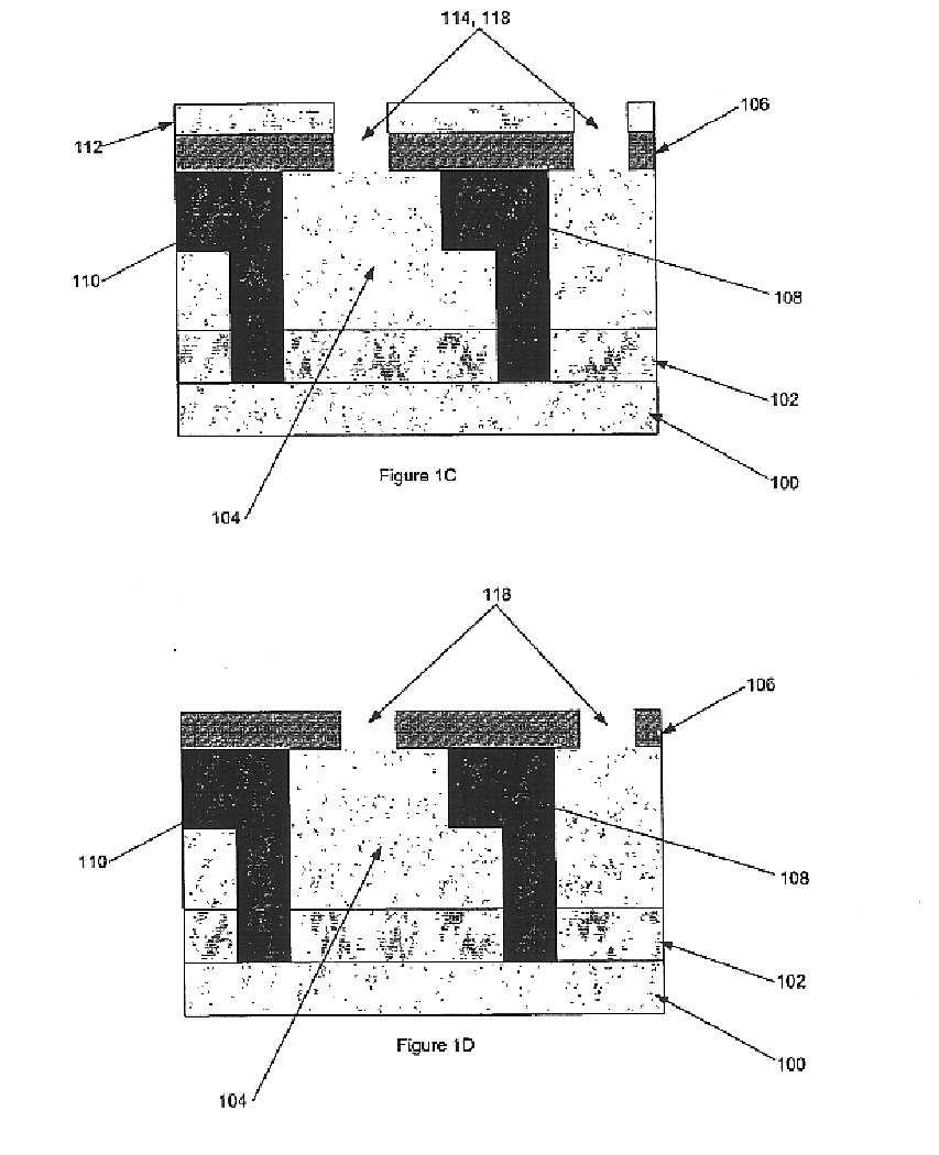
Referring to FIG. 1A, a cross-sectional view of a microelectronic structure is shown having a substrate layer (100) adjacent a first dielectric layer (102), which is depicted adjacent a sacrificial dielectric layer (104). The sacrificial dielectric layer (104), selected for its relatively low dielectric constant, controllable dissolution or decomposition characteristics, compatibility with adjacent materials, and mechanical properties, is positioned between the first dielectric layer (102) and a second dielectric layer (106...


PUM


Abstract

A low-k dielectric sacrificial material is formed within a microelectronic structure covered with a layer defining an exhaust vent. At an appropriate time, the underlying sacrificial material is decomposed and exhausted away through the exhaust vent. Residue from the exhausted sacrificial material accumulates at the vent location during exhaustion until the vent is substantially occluded. As a result, an air gap is created having desirable characteristics as a dielectric.

Description

BACKGROUND OF THE INVENTIONLow dielectric constant materials are used as interlayer dielectrics in microelectronic devices, such as semiconductor devices, to reduce the RC delay and improve device performance. As device sizes continue to shrink, the dielectric constant of the material between metal lines must also decrease to maintain the improvement. Certain low-k materials have been proposed, including various carbon-containing materials such as organic polymers and carbon-doped oxides. Although such materials may serve to lower the dielectric constant, they may offer inferior mechanical properties such as poor strength and low fracture toughness. The eventual limit for a dielectric constant is k=1, which is the value for a vacuum. Methods and structures have been proposed to incorporate void spaces or “air gaps” in attempts to obtain dielectric constants closer to k=1. One major issue facing air gap technology is how to remove sacrificial material to facilitate multi-layer struct...

Claims


Application Information

Patent Timeline
IPC IPC(8): B81B7/00H01L23/52H01L21/70H01L21/02H01L23/522H01L23/532H01L21/768H01L21/311
CPCB81B7/0006H01L21/31127H01L21/7682H01L23/5329H01L23/53295H01L23/5222H01L2924/09701H01L2924/0002
Inventor PARK, HYUN-MOGKLOSTER, GRANT M.
Owner INTEL CORP
Why Eureka
Try Eureka