Half bridge with constant amplitude drive signal

a constant amplitude drive signal and half bridge technology, applied in the direction of climate sustainability, gas discharge lamp usage, light sources, etc., can solve the problems of increased conduction loss in the power stage, loss of zero voltage switching, and high driver loss

a constant amplitude drive signal and half bridge technology, applied in the direction of climate sustainability, gas discharge lamp usage, light sources, etc., can solve the problems of increased conduction loss in the power stage, loss of zero voltage switching, and high driver loss

US6861811B2Inactive Publication Date: 2005-03-01KONINKLIJKE PHILIPS ELECTRONICS NV

Image

  • Half bridge with constant amplitude drive signal
  • Half bridge with constant amplitude drive signal

Examples


Embodiment Construction

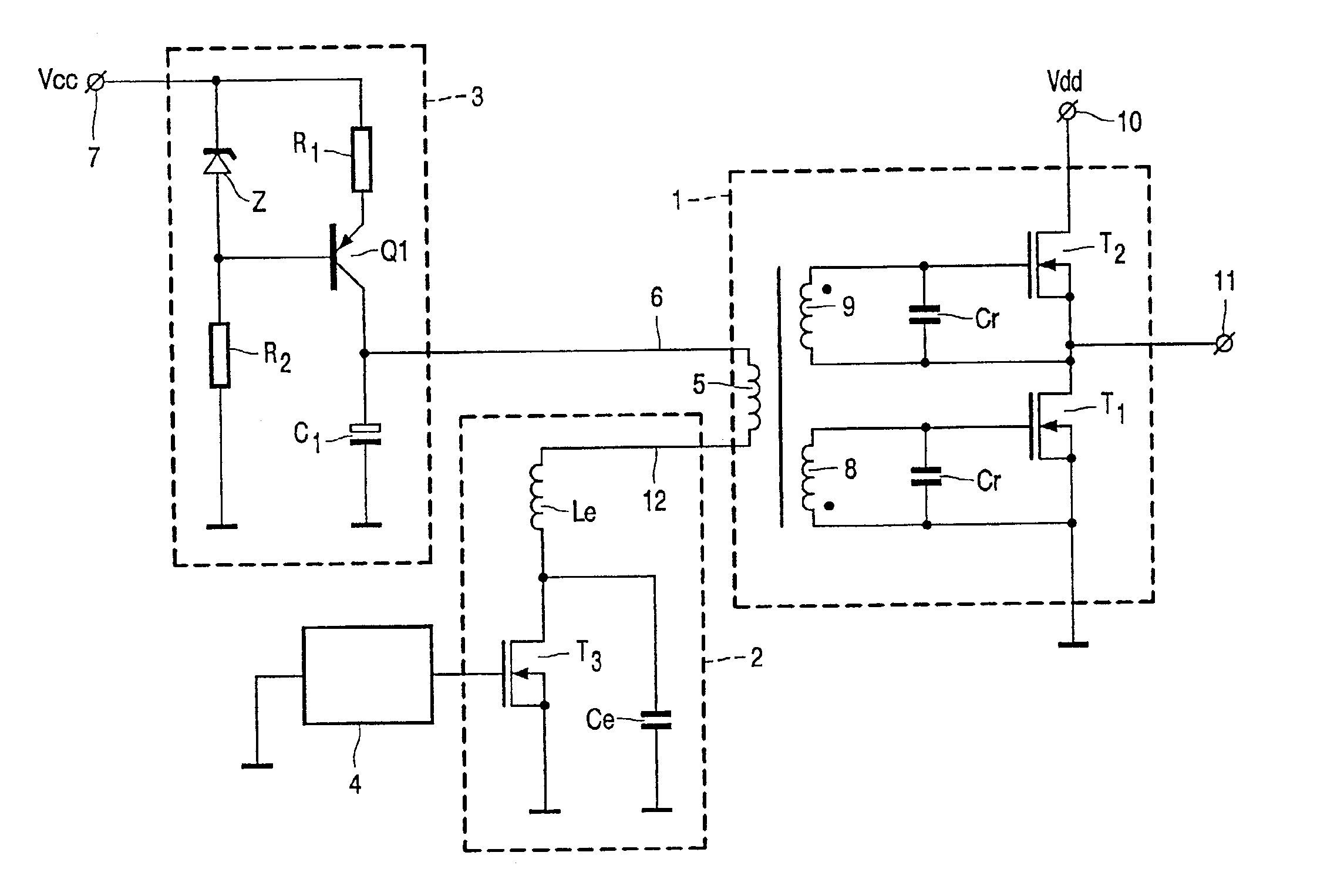
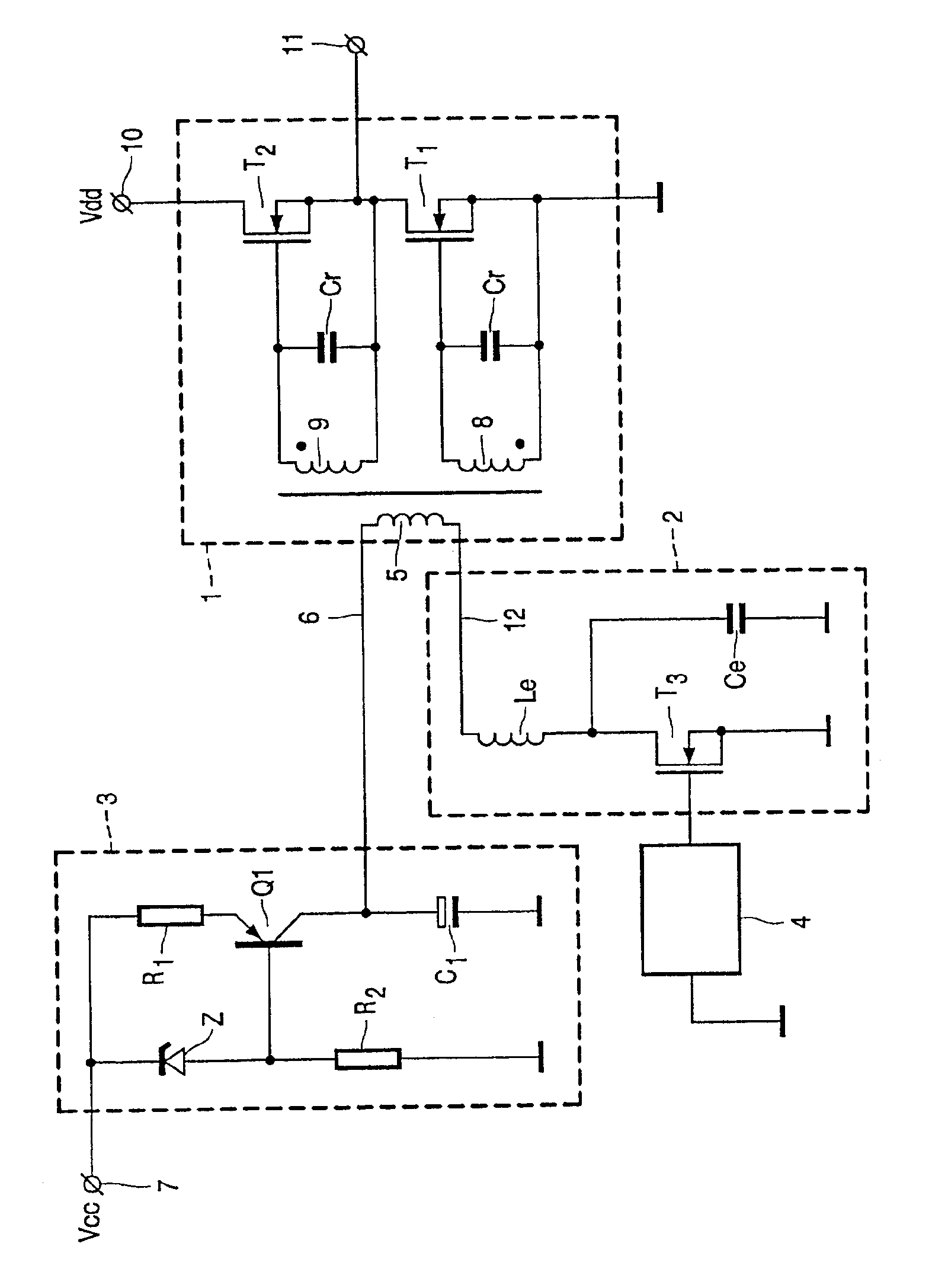
The circuit arrangement according to the FIGURE comprises a power stage 1, a class B driver 2, a current limiter 3 and a voltage control oscillator (VCO) 4, forming the externally driven oscillator.

The power stage 1 comprises two FETs T1, T2, 3NA50, two capacitors Cr of 4.7 nf and a transformer Tr comprising a primary winding 5 and two secondary windings 8,9 with winding ratios 1:1:1. The supply voltage Vdd at terminal 10 has a value of about 400 V.

The lower terminal 12 of primary windings 5 of transformer Tr is connected to class B driver 2, which in turn comprises a FET BSB122, an inductor Le of 1.5 μhy and a capacitor CE of 470 pf. The driver 2 is controlled by a control voltage supplied by VCO 4 of the type HEF4046. The frequency of the output voltage provided by this VCO 4 is about 2.5-2.8 MHz.

The upper terminal 6 of primary winding 5 of transformer Tr is connected to current limiter 3 comprising a transistor Q1 of the type BD136, resistor R1 with a value of 15 Ω, R2 having a v...


PUM


Abstract

The invention concerns a circuit arrangement for igniting and operating an electrodeless gas discharge lamp by means of a high operating frequency drive voltage, comprising a half-bridge commutator having two switching elements each having an emitter electrode and a control electrode. The said switching elements are alternately switched to a conducting state by means of a resonant control circuit, which is coupled to an oscillator via a transformer. The said resonant control circuit comprises capacitor means forming part of said oscillator and a driver stage driven by an oscillator, the driver being of the class-E type. A DC supply voltage is supplied to the driver via a current-limiting circuit. The amplitude of the high frequency drive voltage is substantially constant in a chosen frequency range.

Description

BACKGROUNDThe invention relates to a circuit arrangement for igniting and operating a discharge lamp by means of a high operating frequency drive voltage, said circuit comprising a half-bridge commutator having two switching elements each having an emitter electrode and a control electrode, said switching elements being alternately switched to a conducting state by means of a resonant control circuit which is coupled to an externally driven oscillator via a transformer, said resonant control circuit comprising capacitor means forming part of said oscillator.Such a circuit is known from international patent application WO-A-00 / 21341. The known circuit is used to ignite and operate an electrodeless gas discharge lamp. In the known circuit the half bridge commutator and the resonant control circuit form together a power stage supplying power to the load. In this prior art circuit arrangement, the amplitude of the drive voltage applied to the power stage supplying power to the load, in ...

Claims


Application Information

Patent Timeline
01 Mar 2005
Publication
US6861811B2
IPC
H05B41/28; H05B41/24
CPC
H05B41/2806; Y02B20/22; Y02B20/00
Inventors
BUIJ, ARNOLD WILLEM