System and method for performing diagnostics using a portable device displaying diagnostic data using templates

a portable device and diagnostic data technology, applied in the direction of instrumentation, electrical programme control, program control, etc., can solve the problems of increasing complexity, increasing difficulty, and increasing difficulty in servicing and maintaining such equipment, and achieve the effect of easy creation

Inactive Publication Date: 2005-03-01
RANCO INC
View PDF8 Cites 61 Cited by
  • Summary
  • Abstract
  • Description
  • Claims
  • Application Information

AI Technical Summary

Benefits of technology

The present invention addresses these and other needs by providing an application environment within a portable, or remote, device that utilizes diagnostic modules that are easily created using a diagnostic database development tool.

Problems solved by technology

The number and complexity of appliances and equipment being provisioned at residential and business locations is growing at an unprecedented rate.
Servicing and maintaining such equipment has always been a difficult task that will only become more challenging and complex in the future.
This approach to maintenance and repair relies almost exclusively on the skill of the technician and is becoming more difficult as appliances are equipped with more intelligence.
However, the costs of so many, and so specialized, diagnostic devices make such a solution too expensive and unattractive for most service personnel and companies.
However, there would still be a tremendous cost in developing and coding the numerous customized software applications for each appliance.

Method used


Image

  • System and method for performing diagnostics using a portable device displaying diagnostic data using templates
  • System and method for performing diagnostics using a portable device displaying diagnostic data using templates
  • System and method for performing diagnostics using a portable device displaying diagnostic data using templates

Examples


Embodiment Construction

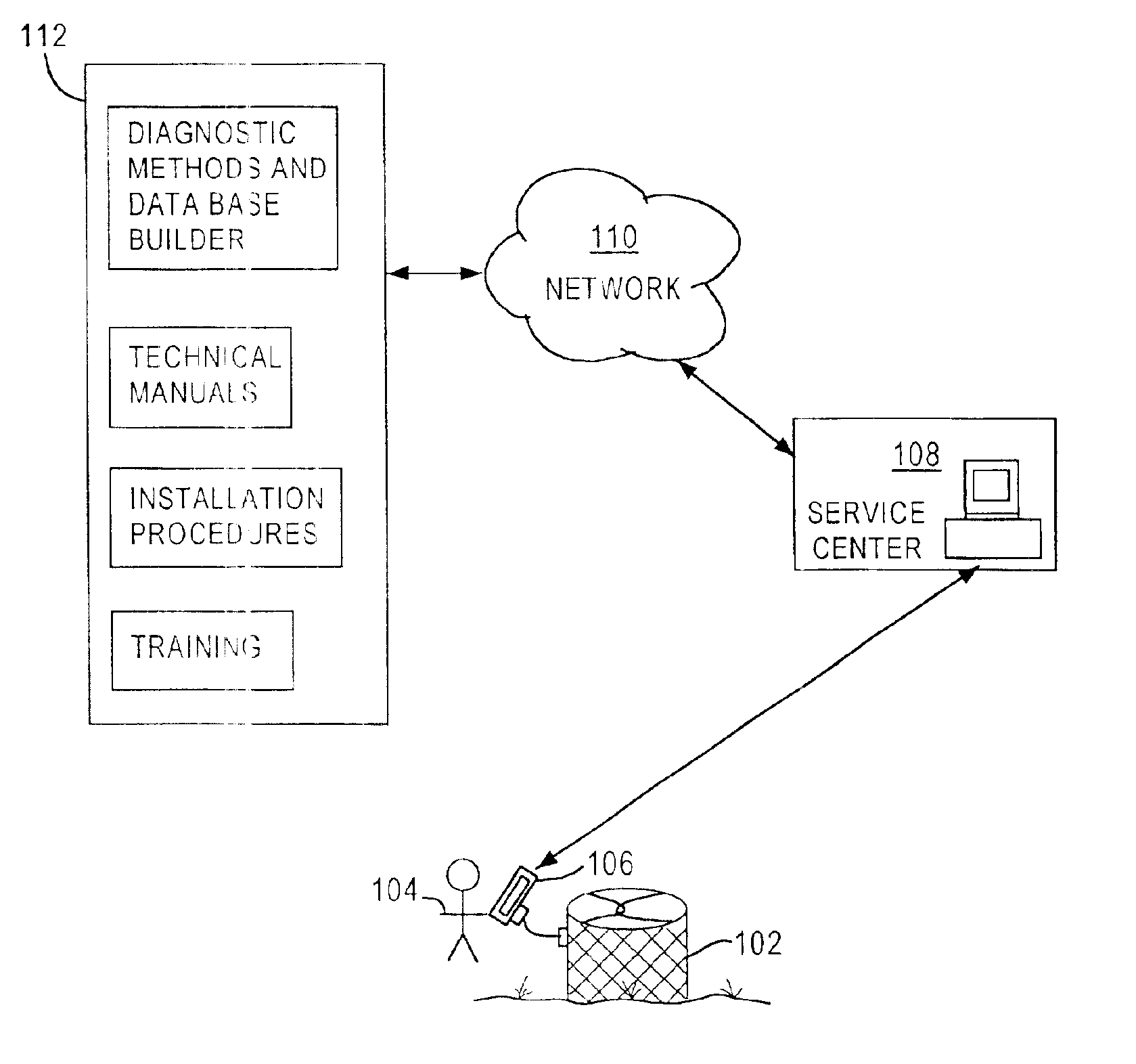
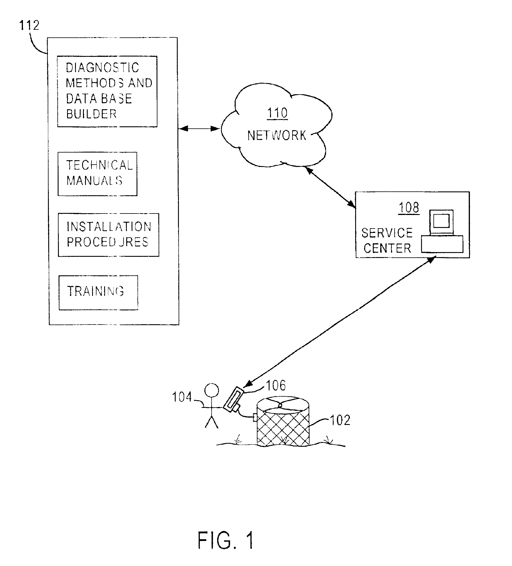
While the present description focuses on an exemplary embodiment of a portable device, such as a PDA, being utilized by a service technician, the present invention also contemplates the use of a remotely-connected computing platform performing similar operations and having similar functionality. Furthermore, the described diagnostic tool and methods can be used connected to an “intelligent” appliance or, alternatively, can operate independently from such an appliance. In the first instance, the diagnostic tool and the appliance can communicate and exchange parameters and values helpful in the diagnoses and repair of the appliance. Possible communications protocols include, for example, RS 232, RS 485, USB, Blue Tooth, TCP / IP, IRda, and Wireless GPS. In the independent operational mode, the diagnostic routines and procedures may be the same but the values and parameters can be manually entered by the on-site technician.

Exemplary Environment

FIG. 1 depicts an exemplary environment in w...


PUM


Abstract

A diagnostic tool suite is made available to technicians servicing equipment at residential and business locations using a portable device such as a PDA. The PDA runs a main engine that can execute diagnostic modules, with each diagnostic module corresponding to a particular appliance or device that requires troubleshooting, repair, diagnosis, maintenance or installation. The diagnostic modules use a limited number of templates to define possible screen layouts for each screen displayed to the technician. Additionally, the diagnostic module includes a diagnostic flow definition file wherein each record corresponds to a screen displayed to a technician. The main engine uses the template information and the diagnostic flow definition records to fully define a screen to display to a technician. In this way, an extensible, modular, non-specific diagnostic tool suite is available to a technician. To simplify creation of the diagnostic definition files, a graphical user development tool is provided that allows a non-skilled user to select a template definition, to be prompted for definitions of the fields in that template and to create the diagnostic definition file incorporating the user's input.

Description

FIELD OF THE INVENTIONThe present invention relates to equipment diagnostic systems and, more particularly, to automated diagnostic systems for heating and cooling equipment.BACKGROUND OF THE INVENTIONThe number and complexity of appliances and equipment being provisioned at residential and business locations is growing at an unprecedented rate. Furthermore, this equipment typically includes microprocessors and other programmable logic that allow interoperation and communication with other appliances as well as remote devices. Servicing and maintaining such equipment has always been a difficult task that will only become more challenging and complex in the future.In the past, a specialized and very skilled and experienced technician was needed that understood the troubleshooting procedures and operation of a variety of appliances as well as the usefulness of different troubleshooting equipment such a volt meters, amp meters, pressure gauges and similar test equipment. This approach ...

Claims


Application Information

Patent Timeline
Patent Type & Authority Patents(United States)
IPC IPC(8): G05B19/19G06F17/30
CPCG05B19/19G06F17/30306G05B2219/23027Y10S707/99933G05B2219/24058G06F16/217
Inventor GRANT, CHARLES
Owner RANCO INC
Why Eureka
Try Eureka