
System and method for eliminating write back to register using dead field indicator

a dead field indicator and register technology, applied in the field of digital computation circuits, can solve the problems of reducing affecting and the write operation of the register file is typically significant, so as to reduce the size or silicon area of the register file, reduce the number of register file write operations, and reduce the overall power consumption of the processor

Inactive Publication Date: 2005-03-01
INVENSAS CORP
View PDF11 Cites 42 Cited by
  • Summary
  • Abstract
  • Description
  • Claims
  • Application Information

AI Technical Summary

Benefits of technology

It is a further object of the invention to provide a processor instruction set architecture that reduces the number of register file write operations in a pipeline method; advantageously, in turn, reducing the overall power consumption of the processor. In addition, the size or silicon area of the register file is reduced due the decease number of write ports being required.

Problems solved by technology

The large register file typically contributes significantly to the overall power consumption.
These shortcomings, in turn, contribute to the power consumption and size of the processor.

Method used


Image

  • System and method for eliminating write back to register using dead field indicator
  • System and method for eliminating write back to register using dead field indicator
  • System and method for eliminating write back to register using dead field indicator

Examples


Embodiment Construction

Some portions of the detailed descriptions that follow are presented in terms of programs or algorithms and symbolic representations of operations on data bits within a computer memory. These algorithmic descriptions and representations are the means used by those skilled in the data processing arts to most effectively convey the substance of their work to others skilled in the art. An algorithm is here, and generally, conceived to be a self-consistent sequence of steps leading to a desired result. The steps are those requiring physical manipulations of physical quantities. Usually, though not necessarily, these quantities take the form of electrical, magnetic or optical signals capable of being stored, transferred, combined, compared, and otherwise manipulated.

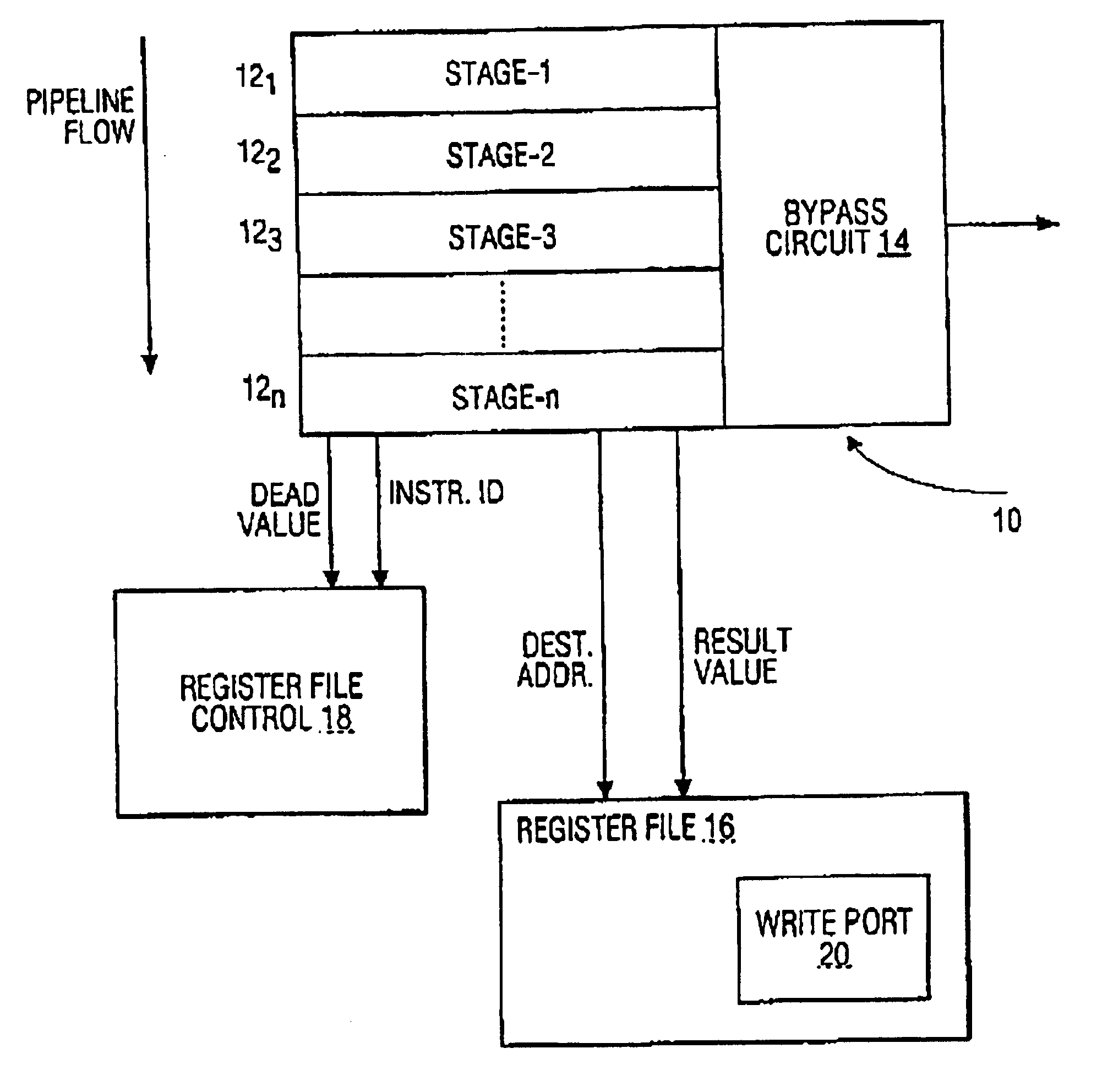
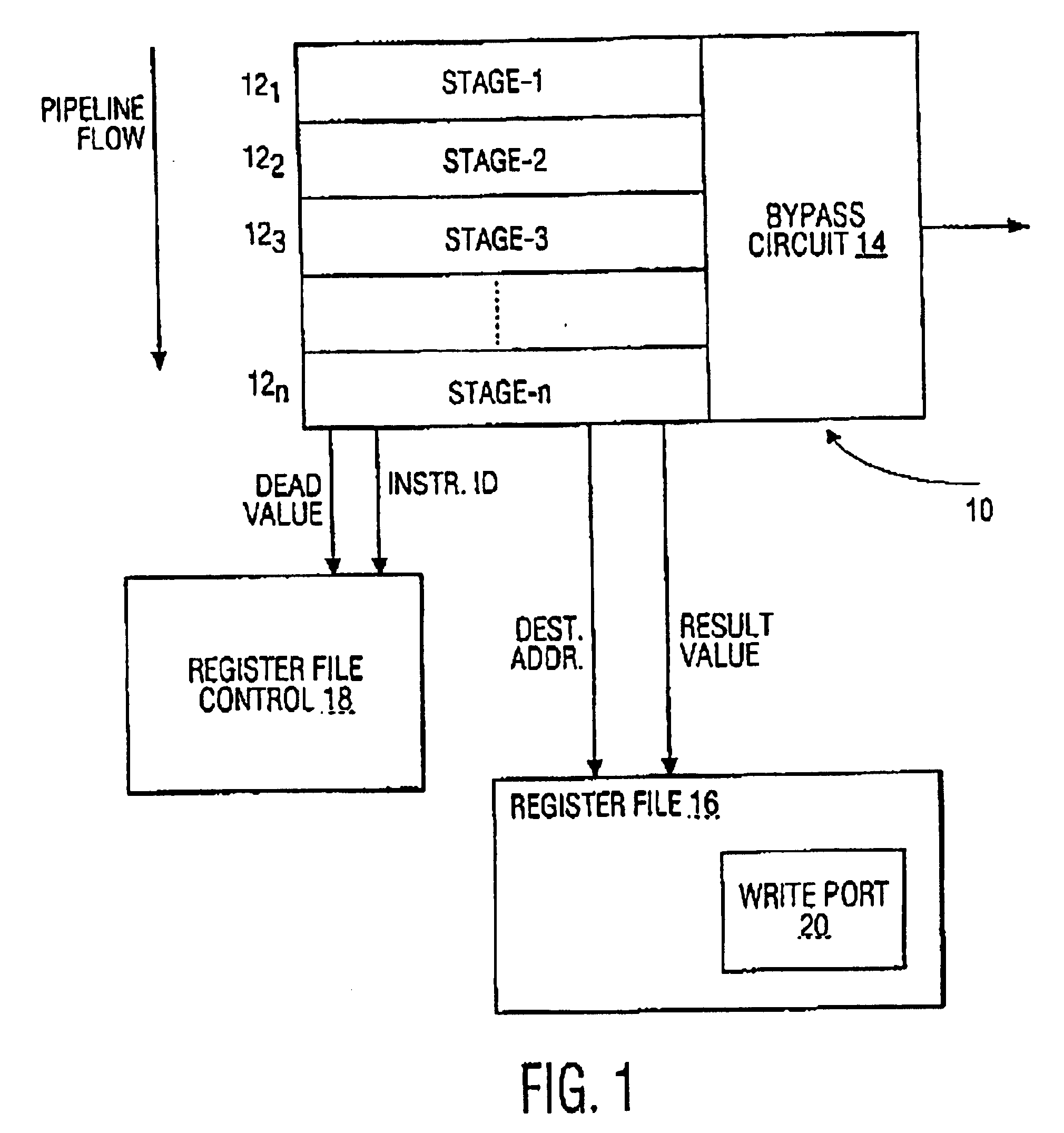
Referring now to FIG. 1, a block diagram is shown for illustrating one embodiment of an instruction execution device in accordance with the teachings of the present invention. It will be recognized that FIG. 1 is simplified f...


PUM


Abstract

An instruction execution device and method are disclosed for reducing register write traffic within a processor. The instruction execution device includes an instruction pipeline for producing a result for an instruction, a register file that includes at least one write port for storing the result, a bypass circuit for allowing access to the result, a means for indicating whether the result is used by only one other instruction, and a register file control for preventing the result from being stored in the write port when the result has been accessed via the bypass circuit and is used by only one other instruction.

Description

FIELD OF THE INVENTIONThe present invention pertains generally to the field of digital computation circuits, and in particular, the invention relates to a system and method for an instruction execution device for use with a processor.BACKGROUND OF THE INVENTIONGeneral motivational criteria exist for the design of microprocessors, for example, to reduce power consumption and size of such devices and as well reducing overall cost. In particular, one technological development in this regard has been the development of instruction execution architectures that implement a number of simultaneous parallel instructions.Systems and methods are known that provide instruction execution architectures of the type noted above, for example, microprocessor Instruction Set Architectures (ISAs). Typically, the implementation of such ISAs employs a so-called “pipeline” method to overlap different execution stages of subsequent instructions.A conventional four-stage pipeline employs a (1) Fetch, (2) De...

Claims


Application Information

Patent Timeline
Patent Type & Authority Patents(United States)
IPC IPC(8): G06F9/38G06F9/318G06F9/30G06F9/34G06F9/45
CPCG06F9/3826G06F9/3873G06F9/3857G06F9/30185G06F9/3832G06F9/3858G06F9/38
Inventor STRAVERS, PAUL
Owner INVENSAS CORP
Learn More