Wear measurement device

a measurement device and wear technology, applied in the direction of measuring material strength using tensile/compressive forces, instruments, structural/machine measurement, etc., can solve the problems of increasing the effective length of the chain or section of the chain, changing the pitch of the chain, and the pin or pins are worn, so as to achieve accurate determination or estimation, accurate determination of the location, and enhanced detection of the pin or pins

Inactive Publication Date: 2005-03-08
FROST TECH
View PDF21 Cites 29 Cited by
  • Summary
  • Abstract
  • Description
  • Claims
  • Application Information

AI Technical Summary

Benefits of technology

Therefore, the present invention provides a pin detection system or wear measurement device or system which is operable to detect a pin or pins of a section of chain and may substantially accurately determine a degree of wear in the pin or pins and/or chain links of the section of chain in response to the detection of the pin or pins. The pins may have a generally pointed extension extending longitudinally from at least one end of the pin or pins for enhanced detection of the pin or pins as the section of chain is conveyed along a conveying path. By detecting the presence of the end of the pin generally along a longitudinal axis of the pin, the present invention provides a substantially accurate determination or estima

Problems solved by technology

As a section of chain bends, the pins may rotate within the openings in the center links and/or side links, which results in wear on both the pins and the center links and/or side links.
The wear leads to an increase in the effective length of the chain or section of chain as well as a change in the pitch of the chain as gaps then may occur between the pins and links.
It is generally undesirable to allow excessive wear in the chain, since this results in slack i

Method used


Image

  • Wear measurement device
  • Wear measurement device
  • Wear measurement device

Examples


Embodiment Construction

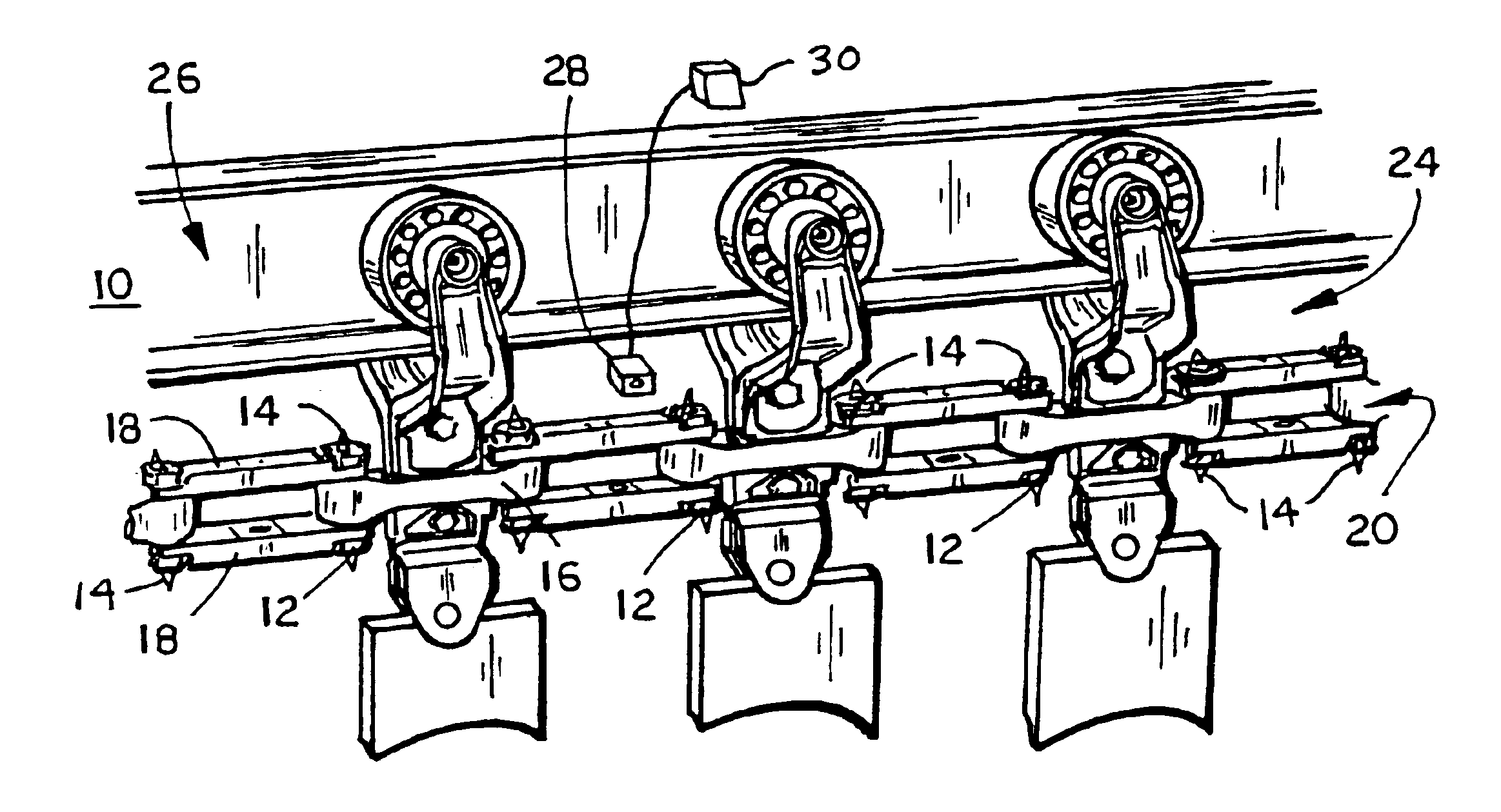
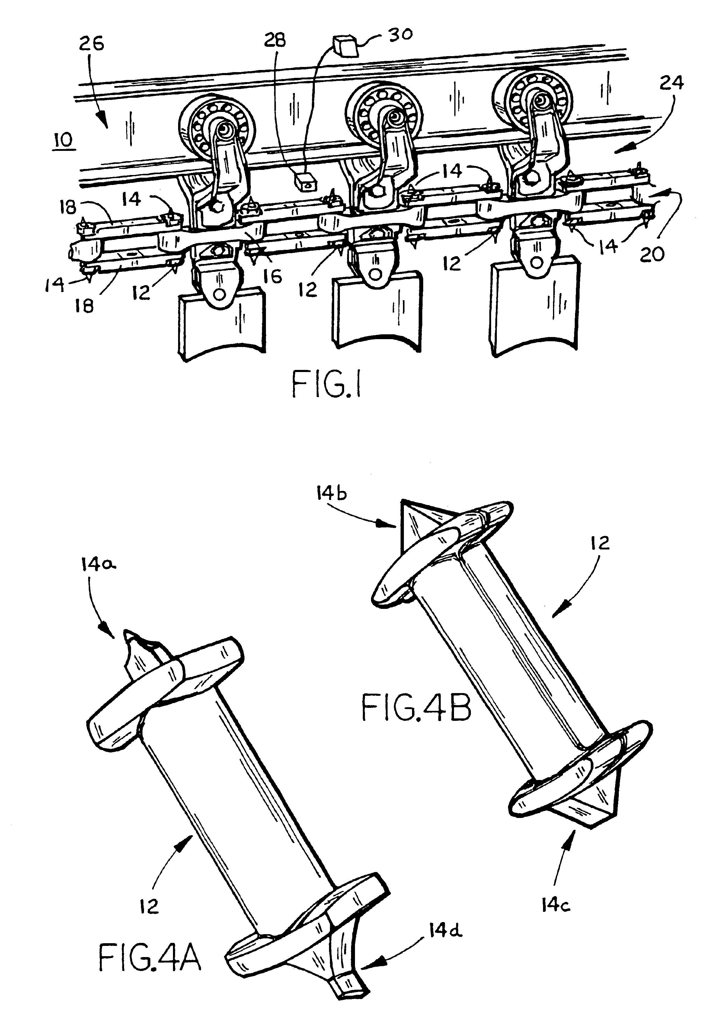
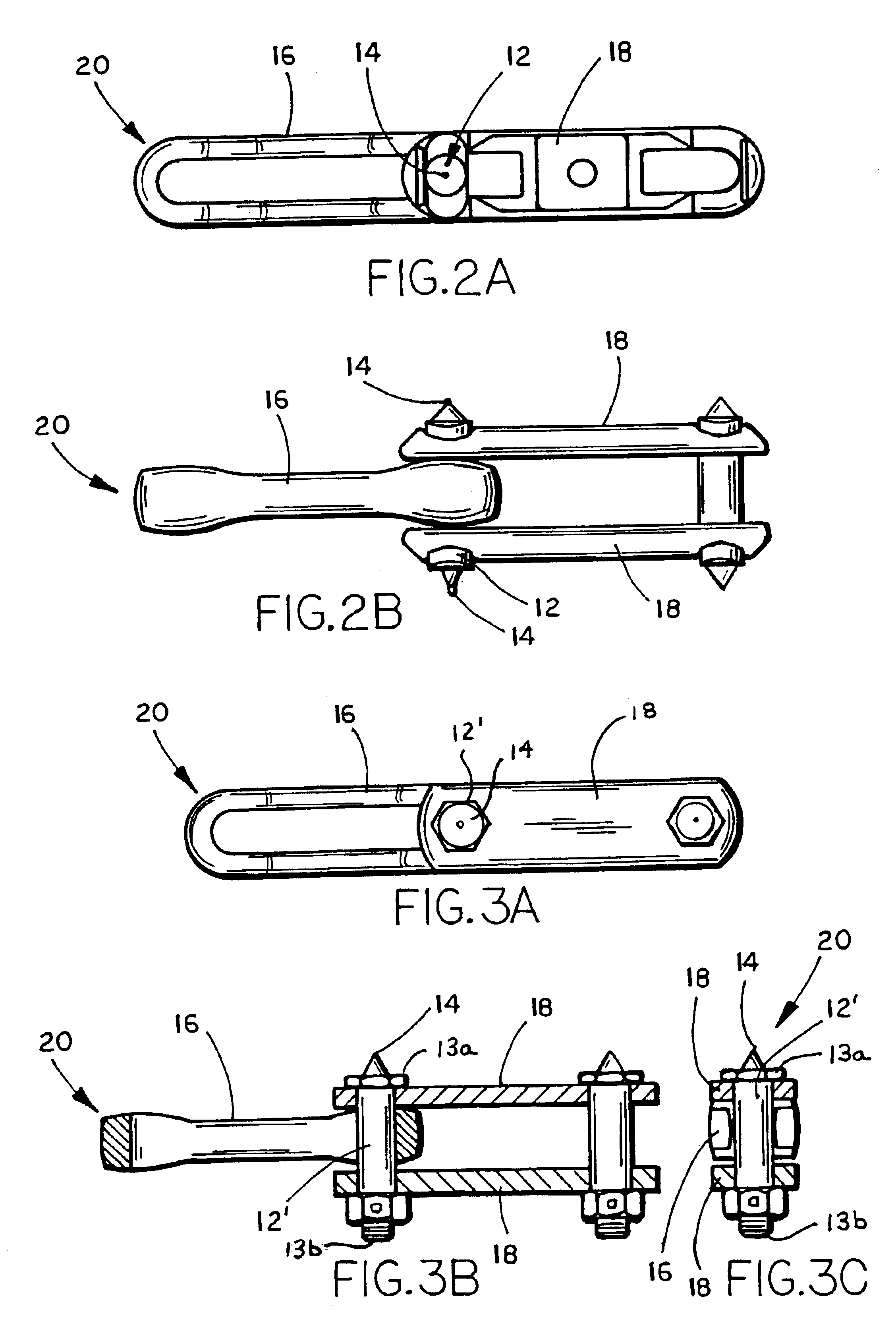
Referring now to the drawings and the illustrative embodiments depicted therein, a pin locating or detecting system or chain wear deduction or measurement device or system 10 includes a pin or pins 12 having an extension 14 extending or projecting from at least one end of at least some of the pins 12 (FIGS. 1-3). Pins 12 connect center links 16 and side links 18 together to form a section or sections of a chain 20, such as in a known manner. Chain wear deduction system 10 includes at least one detector or sensor or trip device 28 for detecting or sensing the pins as the section of chain is conveyed along a conveying path 26. Sensor 28 is provided to detect the raised extension 14 as the section of chain is conveyed past the sensor. The sensor is cooperatively incorporated with a wear monitor system or control (shown generally at 30 in FIG. 1), which may determine the amount of wear in the chain or section of chain in response to the detection of consecutive or spaced raised extensio...


PUM


Abstract

A chain wear measurement system and/or method for determining an amount of wear in a section of chain comprises a chain or section of chain having a plurality of chain links connected together by a plurality of pins or bolts or the like. At least one end of at least one of the pins or bolts may have an extension extending longitudinally therefrom. A sensor is provided along a conveying path of the chain for sensing the presence of the pin or bolt and/or extension as the section of chain is conveyed along the conveying path. The sensor provides a signal indicative of a detection of the pin or pins or bolts. A control may be responsive to the sensor, such as to determine the degree of wear in the section of chain in response to one or more signals from the sensor.

Description

FIELD OF THE INVENTIONThe present invention relates generally to conveyor chains and, more particularly, to methods and / or systems for estimating or determining an amount of wear of the chain links and / or pins or bolts of a conveyor chain or section of chain.BACKGROUND OF THE INVENTIONConveyor chains are known in the art and include a plurality of link pins which connect a plurality of center links and side links to form a continuous conveyor chain for conveying conveyor trolleys or the like along a conveying path. As the chain is moved along the conveying path, the links and sections of the chain undergo bends and turns along a continuous conveying path or chain loop. As a section of chain bends, the pins may rotate within the openings in the center links and / or side links, which results in wear on both the pins and the center links and / or side links. The wear leads to an increase in the effective length of the chain or section of chain as well as a change in the pitch of the chain...

Claims


Application Information

Patent Timeline
IPC IPC(8): G01N3/56G01M13/02G01N3/00G01N3/02G01N3/06
CPCG01M13/023G01N3/56G01N2203/0664G01N2203/0244
Inventor FROST, CHARLES C.
Owner FROST TECH
Why Eureka
Try Eureka