Bicycle suspension

Inactive Publication Date: 2005-03-08
SHIMANO INC
View PDF33 Cites 162 Cited by
  • Summary
  • Abstract
  • Description
  • Claims
  • Application Information

AI Technical Summary

Benefits of technology

One object of the present invention is to provide a computer controlled suspension system for a vehicle, preferably a bi

Problems solved by technology

These suspension assemblies range from very simple to very complex.
These suspension assemblies and systems, however, have been unable to suppress adequately the bucking action that often occurs when a rider traverses a bump or dip.
This bucking effect is more pronounced at higher speeds, often resulting in

Method used


Image

  • Bicycle suspension
  • Bicycle suspension
  • Bicycle suspension

Examples


Example

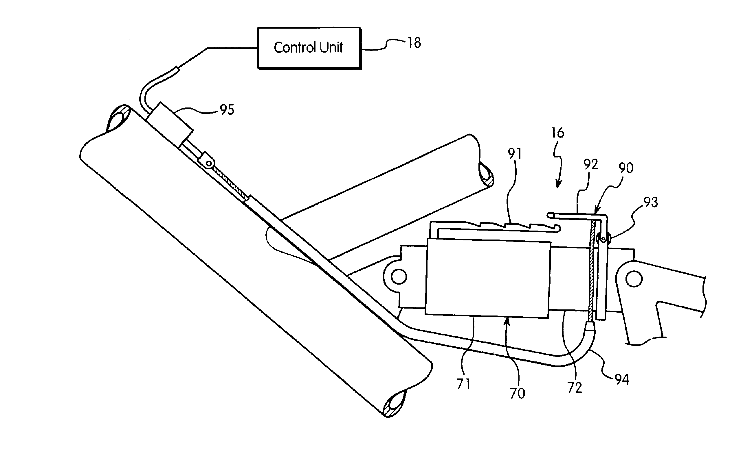
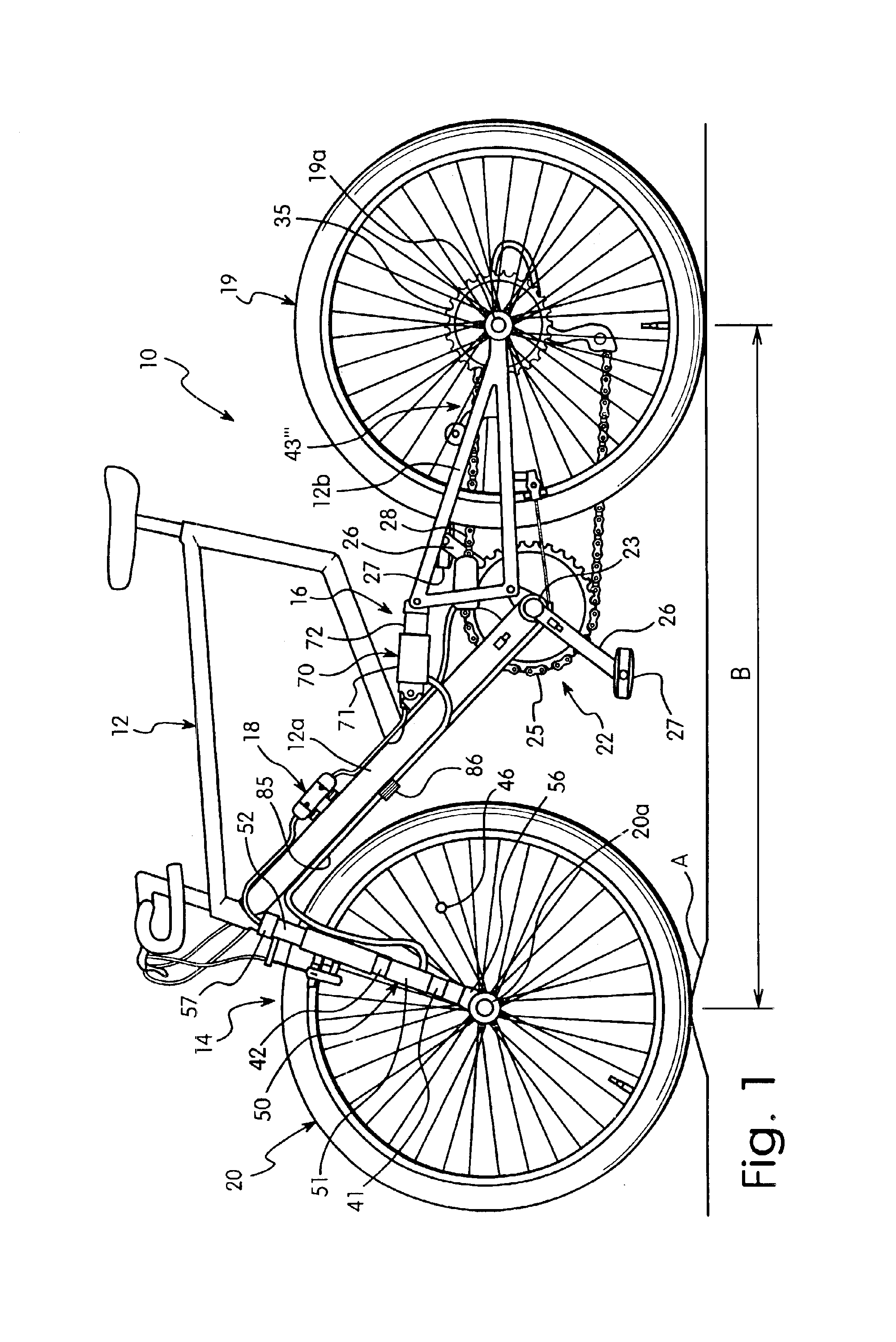
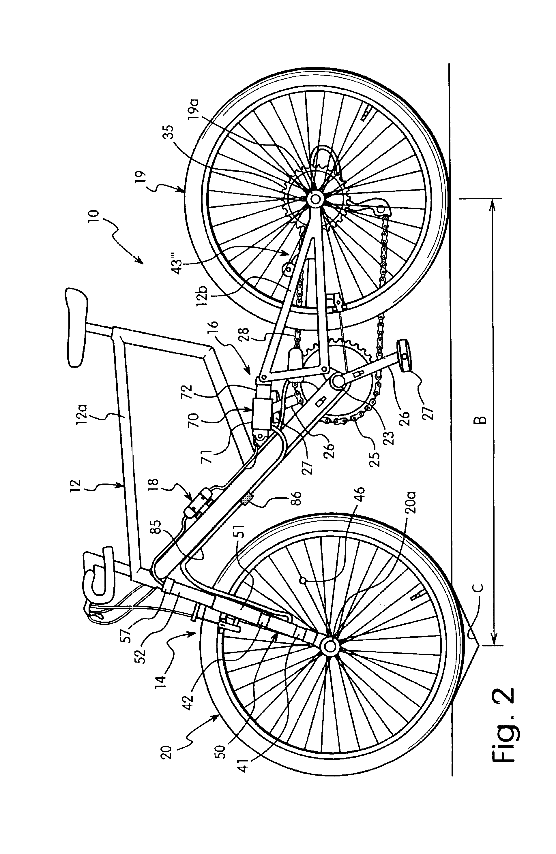
Referring initially to FIGS. 1 and 2, a bicycle 10 is illustrated, which has a frame 12 with a front suspension assembly 14, a rear suspension assembly 16 and a computer or control unit 18 in accordance with the present invention.

The control unit 18 can be installed internally or externally of a part of the bicycle 10. The control unit 18 is preferably a small conventional computer device with a CPU that is operatively connected to the front and rear suspension assemblies 14 and 16, respectively for individually controlling their stiffnesses. When the front tire hits a bump or a depression in the surface of the ground, the front suspension assembly 14 reacts and a signal is sent to the control unit 18 to adjust rear suspension assembly 16 so that the rear suspension assembly 16 can react appropriately.

The bicycle 10 further includes a rear wheel 19 rotatably coupled about rear hub 19a, a front wheel 20 rotatably coupled about front hub 20a and a drive terrain assembly 22 for propell...


PUM


Abstract

A computer controlled suspension system is provided for a bicycle, which can effectively absorb shock and provide stability on rough surfaces regardless of the speed of the vehicle. The suspension system has a control unit, a front suspension, a rear suspension, a front wheel terrain sensor, and a rear controller. The rear suspension is selectively adjustable by the control unit to change stiffness of the rear suspension. When the front suspension hits a bump or a depression in the surface of the ground, a signal is sent to the rear controller so that the rear suspension can react appropriately. In one embodiment, a pedaling torque sensor is operatively coupled to the control unit to input a signal that is indicative of pedaling force, and the rear controller adjusts stiffness of the rear suspension in response to the pedaling force via the control unit. In another embodiment, one or more gear position sensors are operatively coupled to the control unit to input a signal that is indicative of gear position, and the rear controller adjusts stiffness of the rear suspension in response to the gear position force via the control unit. A locking mechanism is provided to operatively coupled to selectively lock the rear suspension in a compressed condition. The front and rear suspension preferably uses at least cylinder with a coil spring and a compressible material located between individual turns of the coil spring.

Description

BACKGROUND OF THE INVENTION1. Field of the InventionThis invention generally relates to suspension systems. More specifically, one aspect of the present invention relates to computer controlled suspension systems for a bicycle.2. Background InformationVarious forms of suspension systems have been developed for vehicles in general and bicycles in particular. Bicycles, especially mountain bikes (MTB) and all terrain bikes (ATB), have been outfitted with front and / or rear suspension assemblies and systems to absorb the shock that would have been transmitted to the rider when riding on a rough road. These suspension assemblies range from very simple to very complex.These suspension assemblies and systems, however, have been unable to suppress adequately the bucking action that often occurs when a rider traverses a bump or dip. This bucking effect is more pronounced at higher speeds, often resulting in the rider losing control and / or being thrown from the bicycle. The reason for this pro...

Claims


Application Information

Patent Timeline
IPC IPC(8): B62K25/28B62K25/30B62K25/04B62K25/08
CPCB62K25/04B62K25/08B62K25/30B62K25/28B62K2025/047B62K2025/044
Inventor MIYOSHI, HIROYUKI
Owner SHIMANO INC
Why Eureka
Try Eureka