Head unit in ink jet printer

a technology of ink jet printer and head unit, which is applied in printing and other directions, can solve the problems of inability to absorb orifice, prone to dot omission, and inability to print correctly, so as to shorten the length of ink passage, shorten the dimension of the head unit, and reduce the effect of print quality

Inactive Publication Date: 2005-03-08
SEIKO EPSON CORP
View PDF15 Cites 18 Cited by
  • Summary
  • Abstract
  • Description
  • Claims
  • Application Information

AI Technical Summary

Benefits of technology

In this configuration, since the damping chamber forming member is provided on the rear face of the head chip, it is possible to shorten the length of an ink passage between the head chip and the damping chamber, i.e., the length of the ink supply port. Accordingly, since the pressure applied to the ink passage accompanying the movement of the head unit can be suppressed, it is possible to obviate a decline in the print quality, such as the dot omission.
If the head chip and the damping chamber forming member are made flat so as to elongate in a direction parallel to the front face of the head chip, it is possible to shorten the dimension of the head unit in the direction perpendicular to the moving direction of the head unit. Since it is possible to reduce the space necessary for the movement of the head unit, the ink jet printer can be made compact.
In the case where the head unit is mounted in a color ink jet printer, a plurality of recesses may be formed in the base member while being arranged in a direction parallel to the front face. Here, it is possible to shorten the ink passage from each damping chamber to the nozzle orifice, and reduce the dimension of the head unit in the direction perpendicular to the moving direction thereof.
In the above configurations, the connection between the damping chamber and the ink supply pipe can be effected by a simple operation in which the ink supply pipe is inserted into the insertion hole of the damper film. In addition, since a sealed state is obtained between the ink supply pipe and the damper film by virtue of the resiliency of the damper film, it is unnecessary to provide another measure for sealing these portions. Accordingly, the operation of assembling the ink supply pipe can be facilitated.
In this configuration, it is possible to obviate the drawback that bubbles which entered the damping chamber through the ink supply pipe are accumulated at the tip portion of the ink supply pipe and obstruct the ink supply.
In this configuration, not only the formation of the ink supply passage to the damping chamber and the assembly of the head unit can be simplified, but also the head unit can be made compact.

Problems solved by technology

If this pressure is applied to a nozzle orifice of the head unit, it becomes impossible to properly discharge ink droplets, which can cause faulty printing such as the splashing of ink droplets, dot omission or the like.
However, the pressure which can be absorbed by the damper mechanism mounted in the head unit is the pressure acting in the ink passage between the damper mechanism and the ink tank, and the pressure acting in the ink passage from the damper mechanism to the nozzle orifice cannot be absorbed.
Hence, such drawbacks as the dot omission have been liable to occur.
In addition, the head unit having a shape in which it is elongated in the direction perpendicular to the moving direction requires much space for its movement, which has constituted a hindrance to the effort to make the ink jet printer compact.

Method used


Image

  • Head unit in ink jet printer
  • Head unit in ink jet printer
  • Head unit in ink jet printer

Examples


Embodiment Construction

Referring now to the drawings, a description will be given of one preferred embodiment of a head unit for an ink jet printer.

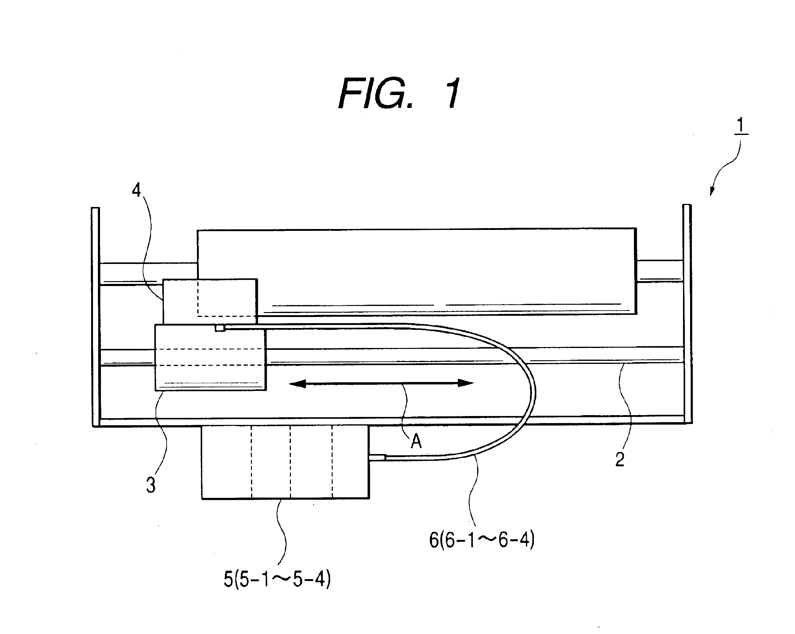
As shown in FIG. 1, an ink jet printer 1 in this embodiment is of a serial type, and a head unit 4 is mounted on a carriage 3 capable of reciprocating along a guide shaft 2. Ink is supplied to this head unit 4 through a flexible ink tube 6 from an ink tank 5 disposed in a predetermined position. In this embodiment, ink of four colors including cyan, magenta, yellow, and black is supplied from ink tanks 5-1 to 5-4, in which the ink is respectively stored, to the head unit 4 through four ink tubes 6-1 to 6-4.

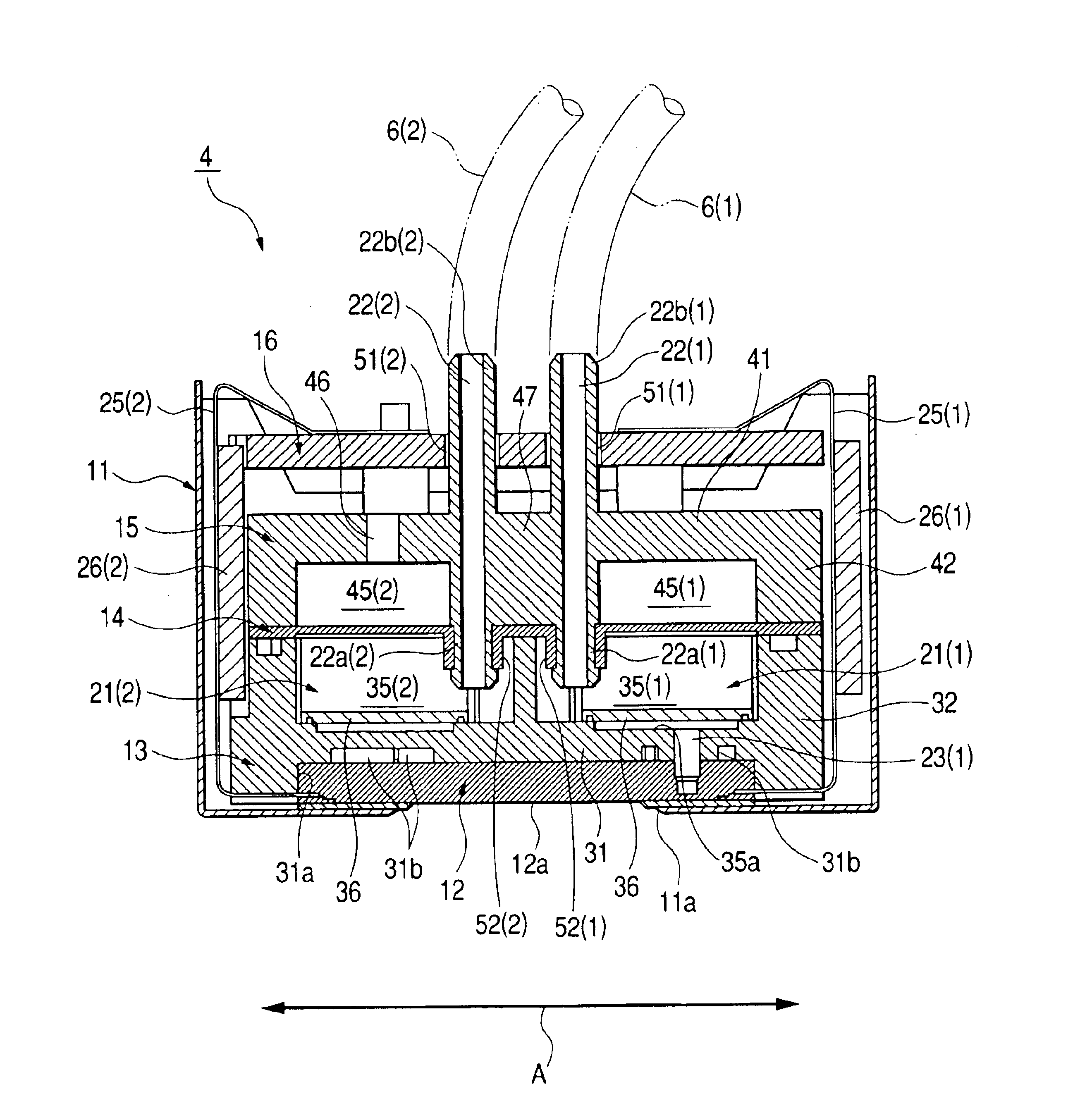
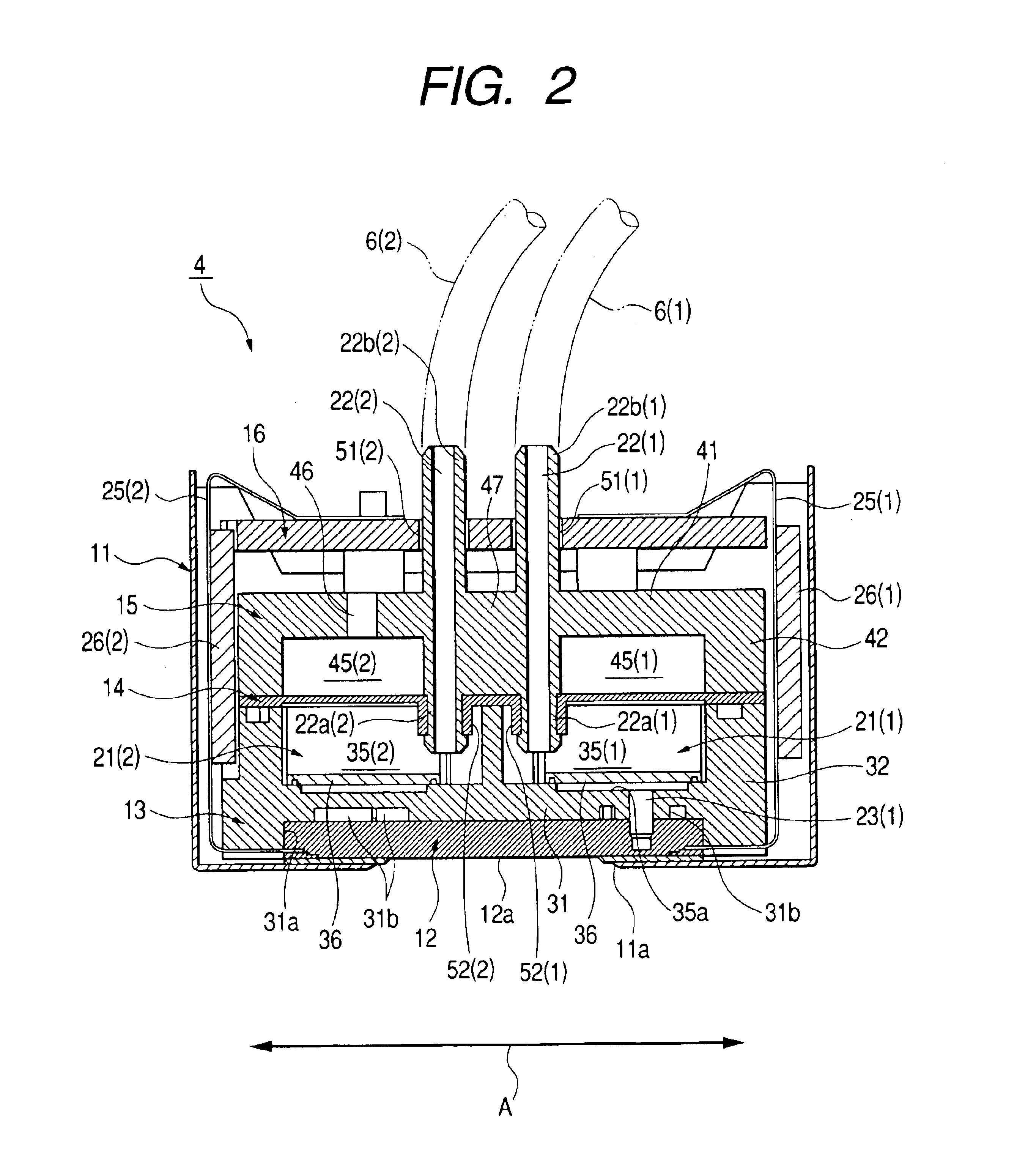
The head unit 4 will be explained in detail with reference to FIGS. 2 through 3D. The head unit 4 of this embodiment has a unit cover 11 whose rear face side is open and which has the shape of a rectangular parallelepiped, and a head-unit assembly is accommodated in this unit cover 11.

A head chip 12, a unit base 13, a damper film 14 made of rubber, a damper ...


PUM


Abstract

A head chip has a front face formed with nozzle orifices, and a rear face formed with at least one ink inlet. A damping chamber forming member is laminated on the rear face of the head chip. The damping chamber forming member has at least one damping chamber for dampening pressure fluctuation occurred therein, and an ink supply port for supplying ink from the damping chamber to the head chip.

Description

BACKGROUND OF THE INVENTIONThe present invention relates to a head unit for a serial type ink jet printer to which ink is supplied from an ink tank, and more particularly to a head unit having a damper mechanism capable of reliably suppressing the fluctuation of ink pressure occurring due to the movement of the head unit. The present invention also relates to an ink jet printer incorporating such a head unit.In a serial type ink jet printer having a construction in which an ink tank and a head unit mounted on a carriage are connected by a flexible ink tube, when the head unit is moved by the carriage, pressure is applied to the ink which is supplied to the head unit. This pressure is largely dependent on the acceleration of the head unit, the length of an ink passage from the ink tank to the head unit, and the specific weight of the ink. If this pressure is applied to a nozzle orifice of the head unit, it becomes impossible to properly discharge ink droplets, which can cause faulty ...

Claims


Application Information

Patent Timeline
Patent Type & Authority Patents(United States)
IPC IPC(8): B41J2/055B41J2/14B41J2/175
CPCB41J2/055B41J2/14B41J2/17513B41J2/17509B41J2002/14419B41J2002/14362B41J2/175
Inventor ARAI, KENICHIROOTSUKI, NOBORU
Owner SEIKO EPSON CORP
Why Eureka
Try Eureka