Crash cushion with deflector skin

a cushion and deflector technology, applied in the field of crash cushions, can solve the problems of relatively expensive structural rigid plates of fish scales, and achieve the effect of less friction coefficient and not as easily gouged

Inactive Publication Date: 2005-03-08
ENERGY ABSORPTION SYST
View PDF19 Cites 39 Cited by
  • Summary
  • Abstract
  • Description
  • Claims
  • Application Information

AI Technical Summary

Benefits of technology

The various preferred embodiments provide significant advantages over other crash cushions. In particular, the cylinders can each be individually configured with one or more deflector skins. Accordingly, the cylinders can be easily arranged or configured in different arrays without expensive customization. Moreover, if one or more cylinders or deflector skins are damaged, they can be easily replaced.
The inner, curved deflector skins also provide the advantage of providing a lower coefficient of friction than the underlying cylinder, such that the vehicle tends to slide along the deflector skin. Moreover, the deflector skin acts as armor plating, and is not as easily gouged as the underlying cylinder, so as to further avoid snagging of the impacting vehicle. Preferably, the inner deflector skin is thinner than the outer deflector skin, and thereby can bend and deform with the cylinder during a frontal impact. Moreover, the positioning of the deflector skins provides discrete protection for the cylinders in the area vulnerable to a lateral impact, yet does not interfere with the overall operation of the system.

Problems solved by technology

However, during a lateral impact, the vehicle may tend to snag or pocket one or more of the cylinders at gaps formed between the outer curved surfaces of adjacent cylinders.
The fish scales are relatively expensive structurally rigid plates that are attached to the cylinders in a relatively complex manner.

Method used


Image

  • Crash cushion with deflector skin
  • Crash cushion with deflector skin
  • Crash cushion with deflector skin

Examples


Embodiment Construction

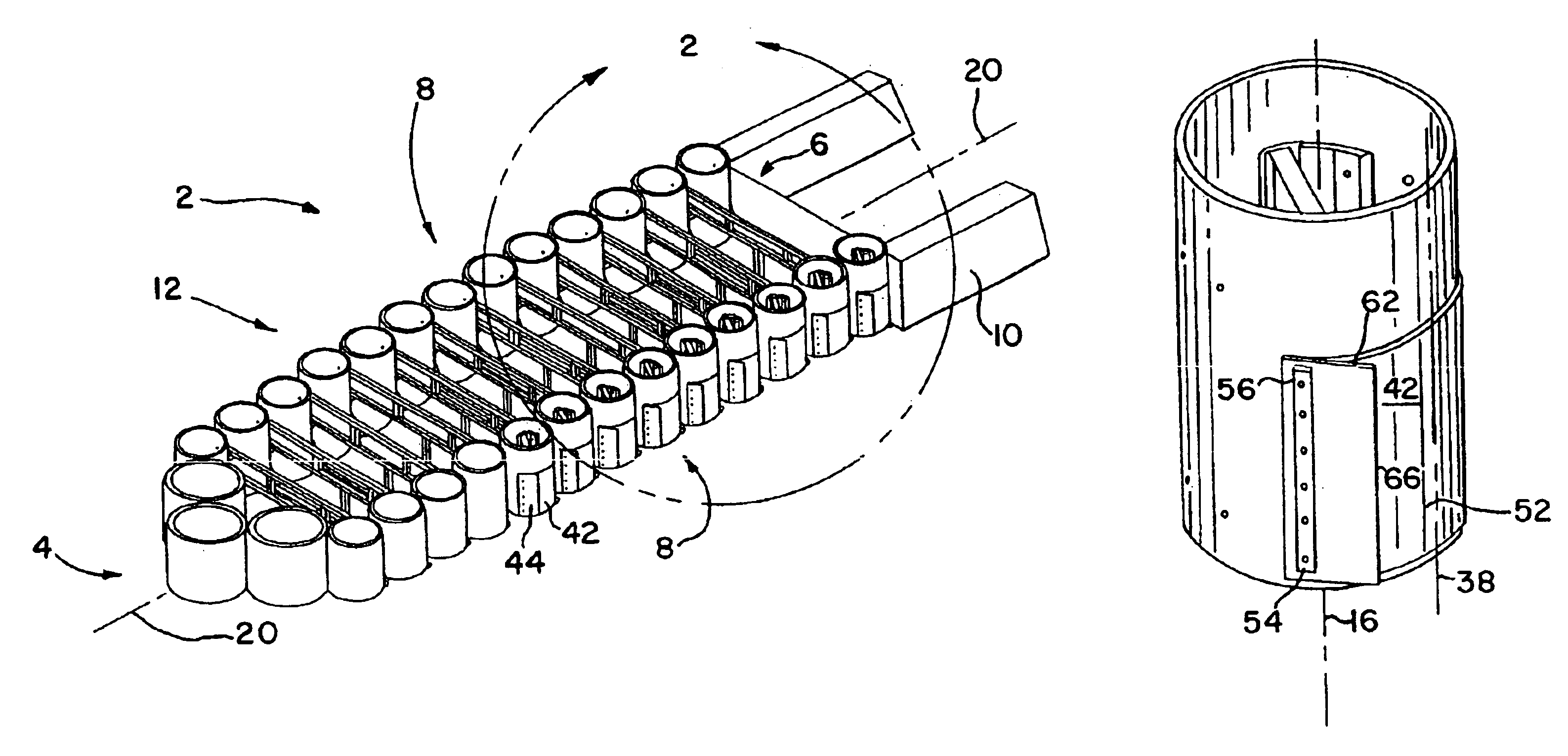
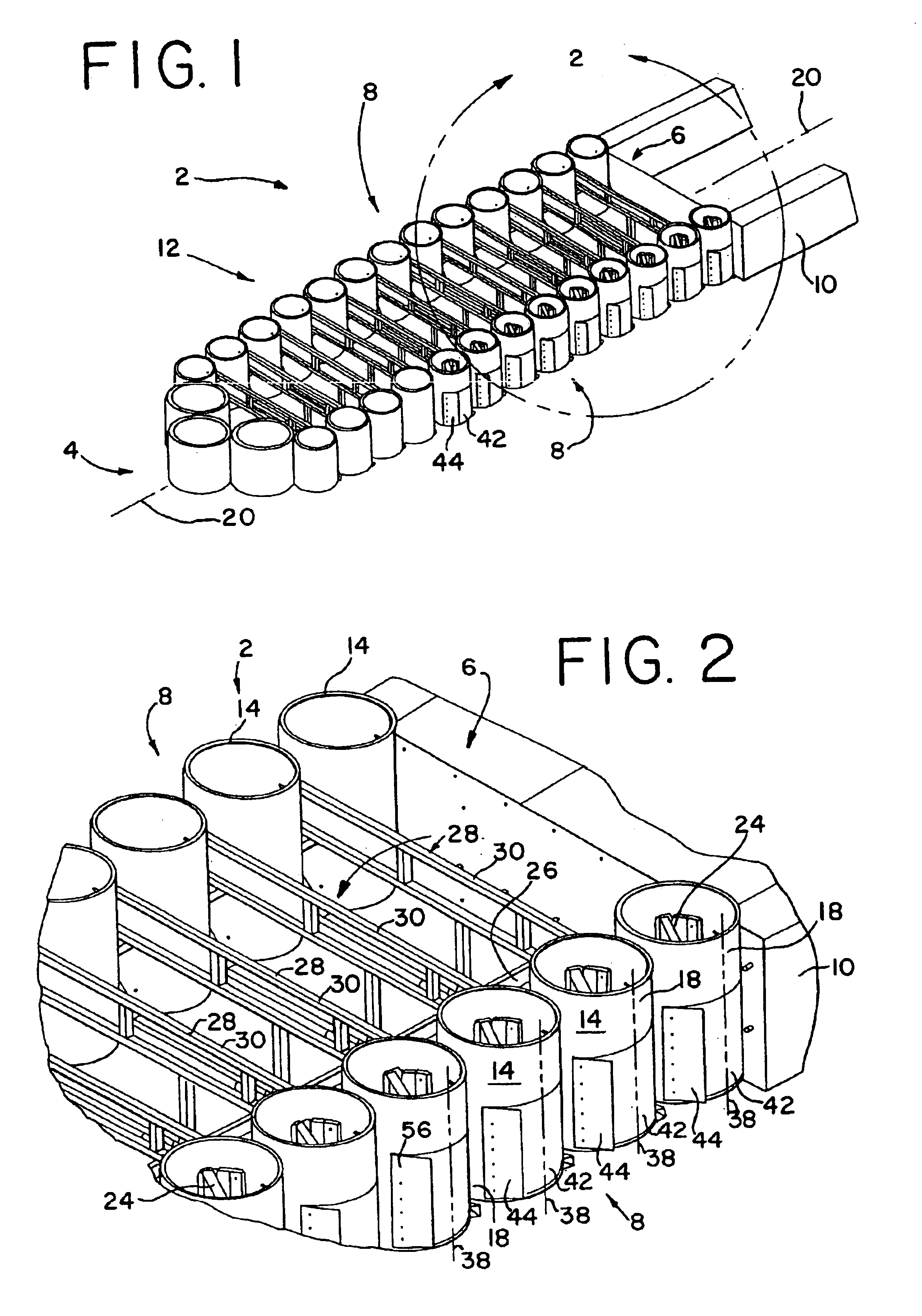
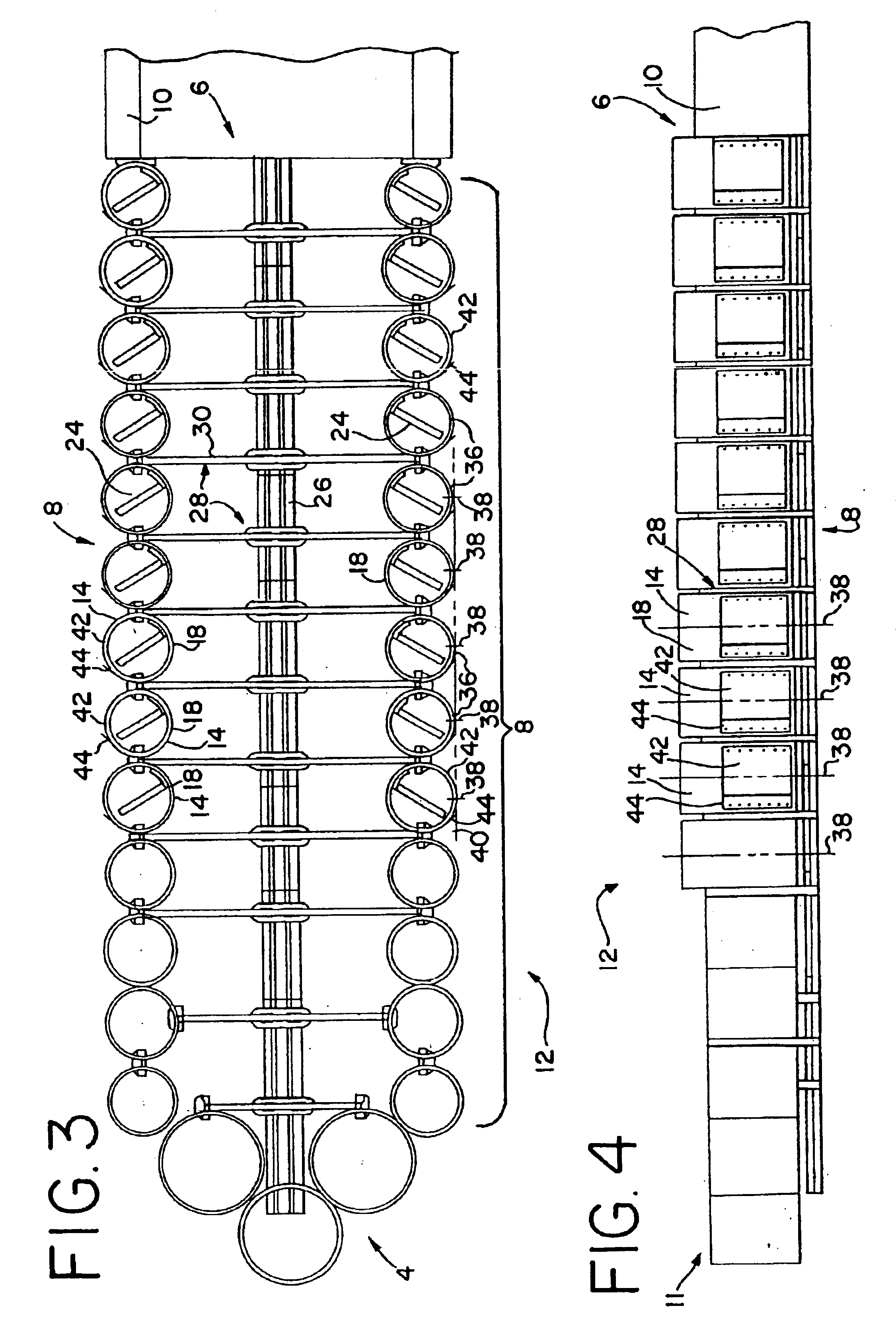
Referring to FIGS. 1-4, one preferred embodiment of a crash cushion 2, otherwise referred to as a vehicle impact attenuator, is shown in an initial position, prior to impact. The crash cushion 2 has a front 4 facing the flow of oncoming traffic and a rear 6 positioned adjacent to a backup 10, which can be any hazard alongside a roadway. Typically, the backup 10 is a rigid object, such as a bridge abutment, tollbooth, wall, guardrail, moving vehicle such as a truck, or other obstruction positioned in or along the roadway. The crash cushion 2 also has a pair of opposite sides 8, at least one of which is exposed to the roadway and the flow of traffic. In one embodiment, shown in FIGS. 1-4, both of the sides 8 are exposed to the traffic flow, for example when the crash cushion 2 is positioned in front of a tollbooth. In other embodiments, the crash cushion 2 may have only one side exposed to the traffic, with the other side facing away from the traveled lanes of the roadway, and which m...


PUM


Abstract

A crash cushion comprising a resilient cylinder having a substantially vertical longitudinal axis and an outer surface at least a portion of which is adapted to be exposed in or to a roadway. A deflector skin has a curved contour shaped to mate with the outer surface of the cylinder. The deflector skin is mounted on the outer surface over at least a portion of the portion of the outer surface that is adapted to be exposed to the roadway. A crash cushion system includes an array of cylinders and at least one deflector skin. In another aspect, a plurality of cylinders, at least some of which define a side of the array, each have an outermost vertical tangent, the combination of which defines a vertical plane. One or more deflector skins each including a leading edge and a trailing edge are mounted to corresponding ones of the cylinders forwardly of the tangent. In one preferred embodiment, the one or more deflector skins are substantially flat and are oriented in a non-parallel relationship with the vertical plane. Preferably, only the leading edge of the deflector skins is mounted to the cylinder. Methods for using and assembling the crash cushion systems are also provided.

Description

BACKGROUNDThe present invention relates to a crash cushion, and in particular to a crash cushion having one or more deflector skins adapted to redirect a laterally impacting vehicle, and methods for the use thereof.Roadways are often configured or lined with protective crash barriers that protect drivers from various rigid objects, such as bridge abutments, guardrails and other obstructions. Likewise, slow moving vehicles, such as trucks, can be outfitted with truck-mounted attenuators to attenuate the impact of vehicle striking them from the rear. In various configurations, highway crash barriers and truck-mounted attenuators can be constructed of an array of compressible, resilient, energy-absorbing cylinders positioned in front of or alongside the rigid object. In operation, and in particular during an axial impact, the cylinders are compressed and absorb the energy of the impacting vehicle, thereby decelerating the vehicle in a controlled manner. However, during a lateral impact...

Claims


Application Information

Patent Timeline
Patent Type & Authority Patents(United States)
IPC IPC(8): E01F15/00E01F15/14B60R21/02
CPCE01F15/148E01F15/146E01F15/00E01F15/14
Inventor BUEHLER, MICHAEL J.WELCH, JAMES B.
Owner ENERGY ABSORPTION SYST
Why Eureka
Try Eureka